| 122.
#include Directive This directive is used to insert the contents of another file into a HTML page. SSI Directive Description Inserts the contents of the file rel-file (specified as a relative path, e.g. footer.htm) into the current HTML page. Inserts the contents of the file abs-file (specified as an absolute path, e.g. b:\events\event.log) into the current HTML page. The #include directive may be nested, i.e.
The SHTML mark-up for this page is as follows: My Custom dataTaker Web Page My Custom dataTaker Web Page  Job Name: Schedule Name: Channel Variable (1CV): Notice the SSI directives (red). Note: The SHTML page filename must be saved with the following extensions:- .shtml, .shm or .sht.
Part J – Modbus Interface About Modbus Modbus is a simple communications protocol which is widely used in SCADA (supervisory control and data acquisition) systems. Modbus provides an efficient and standardised way to transport digital states and data values between a remote terminal unit (RTU) or programmable logic controller (PLC) and a supervisory computer. Servers and Clients In a Modbus-based SCADA system, each RTU/PLC acts as a Modbus server, or slave.
Serial Sensor Port The serial sensor port can be used to connect to a Modbus client via a multi-drop (RS422/ 485) or point-to-point (RS232/ 422/ 485) link. In order to use Modbus on the serial sensor port it is necessary to set the port function, as follows: PROFILE SERSEN_PORT FUNCTION=MODBUS You may also need to configure the baud rate or other serial parameters to suit the system to which you are connecting.
Furthermore, it is common for the different register arrays to overlap. In the example device mentioned above, the 16 coils and discrete inputs may actually refer to the same physical hardware – in this case 16 bi-directional I/O pins. So for this slave device, if a client wrote a "1" to coil 0:00007, it would then read the same value back if it did a read from discrete input 1:00007.
There are, however, a number of options for dealing with data values that cannot be represented by a 16-bit integer value: • the register can be treated as an unsigned 16-bit integer (0-65535) • the value can be scaled, typically by a power of ten, to give the required precision or range. For example a scaling factor of 100 would permit values in the range -327.68 to 327.67 to be returned • multiple registers can be combined to return a single larger value, e.g.
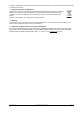
If a Modbus client then requests input registers 3:00007-3:00012 it will receive the following raw data: Register Value (hex / decimal) 3:00007 47AE Comments 3:00008 41BF 3:00009 BF7E / 49022 490.22 multiplied by scaling factor (100) 3:00010 FFFF / 65535 overflow: 921.0 x 100 = 92100 is too big for an unsigned 16-bit integer 3:00011 0001 / 1 3:00012 2710 / 10000 The 32-bit value 41BF47AE is the IEEE754 representation of 23.
This job sets up the following CVs for access by the Modbus client: 1CV, 2CV and 3CV contain the three measured temperatures. A scaling factor of 10.0 is applied so that it can • be returned with one decimal place (range -3276.8 to +3276.7) • 4CV is designed to be accessed as an output register, i.e. the Modbus client writes to it. This channel variable is used as the temperature setpoint, so it is scaled in the same way as the other temperature CVs.
So the setup for this application might be something like: Mimic Element Modbus Reg Data Type Device Range Display Range Units Comments "temp1" 3:00001 signed 16-bit -3276 to 3276 -327.6 to 327.6 degC 1CV (input reg) "temp2" 3:00002 signed 16-bit -3276 to 3276 -327.6 to 327.6 degC 2CV (input reg) "temp3" 3:00003 signed 16-bit -3276 to 3276 -327.6 to 327.6 degC 3CV (input reg) "setpt" 4:00004 signed 16-bit -3276 to 3276 -327.6 to 327.
Part K – Communications Overview The DT80 is very flexible and provides many communications options. To understand how these fit together and what combinations are possible, it is helpful to think of communications in terms of the following hierarchy: • Clients are software programs (e.g. a web browser, or the job running on the logger) that initiate communications to or from the DT80. • These clients use services that are provided by the logger (e.g. web server, command interface).
• PPP (point to point protocol), which allows a TCP/IP connection to be established over a serial link. This then provides similar capabilities to the Ethernet port, i.e. all TCP/IP-based protocols can then operate using this link. On DT8xM models, the DT80 uses PPP to connect to the mobile network. On standard models, the DT80 implements a PPP server on the serial ports. A PPP client (e.g.
Figure 71: DT80 communications options UM-0085-B09 RG DT80 Range User Manual Page 184
Figure 72: DT80 communications options (integrated modem models) UM-0085-B09 RG DT80 Range User Manual Page 185
The Command Interface Connecting to the Command Interface As shown in Figure 71 (P184), the command interface can operate over a serial link ("serial command" protocol), and/or over a TCP/IP network ("network command" protocol).
Setting and Removing the Command Interface Password Set a password by sending PASSWORD="password" to the DT80 password can be any text string of up to 10 case-sensitive characters. Remove a password by sending PASSWORD="" Note: The password is cleared if the DT80 performs a hardware or HRESET reset. Accessing Password-Protected Command Interface To establish communication at any time, simply send the password followed by a carriage return.
Figure 73: Using DtUsb to communicate with the DT80 over USB Note: only one of these interfaces can be active at any one time. By default, the TCP/IP interface will be active, so when the logger USB cable is plugged in, the logger will then become visible at IP address 127.1.1.1 (this address may vary). If, however, you shut down the TCP/IP part of DtUsb then the logger's virtual COM port (shown as COM6 in the diagram) will become available. See USB Direct Serial Mode (P192).
3. Select DT80 range... 4. Select Install USB driver 5. DtUsb actually consists of two parts: DtUsb Driver (the low level "plug and play" USB driver) and DtUsb (which provides the TCP/IP interface). Both of these will now be installed, starting with DtUsb Driver.
6. After the drivers have been copied to your computer a confirmation screen similar to the following will be displayed. Check that two green ticks are displayed. Click Finish 7. The DtUsb installer will now start. If you are installing from the CD and do not have .NET 2.0 or later on your computer it will now be installed (after you accept the Microsoft license agreement), then the DtUsb installer will continue. (If you are using a downloaded DtUsb package then the installer will terminate if .
9. Now connect the DT80 to the computer using the USB cable. This will trigger the Windows "plug and play" process to complete driver installation. You may notice a flurry of activity in the system tray area. The actual sequence of events depends on your operating system. • For Windows XP, the drivers that you pre-installed in Step 5 will be automatically installed with a minimum of fuss.
• Quit will terminate DtUsb, which will mean that the logger's TCP/IP services will no longer be available. This should normally only be used if you wish to use the direct "COM port" interface to the logger, rather than the TCP/IP interface. • Hide will close the GUI, but DtUsb will keep running. Closing the window with the red X button will do the same thing. • Apply will apply any changes you have made on the Configuration tab.
Figure 76: Determining USB COM port number in Device Manager Note: DtUsb must still be installed (but not running) in order to use the USB port in direct serial mode. If it is not installed then the DT80 will not be recognised and a COM port will not be assigned to it. Sleep Mode If the DT80 enters low power sleep mode then its USB interface will be reset. To the host computer, it will look like the USB cable has been unplugged, so the configured COM port will disappear.
Software Flow Control In this mode, the receiver controls the flow of characters by transmitting • the XOFF character (ASCII 19) to stop the sender from sending further characters • the XON character (ASCII 17) to allow the sender to resume sending characters. If the DT80 receives an XOFF character, it will stop transmission within two character periods. If no XON is received within 60 seconds (see PARAMETERS P26 (P260)) the DT80 will resume transmitting anyway.
Host RS-232 Port Not applicable to DT82EM/ 80LM/ 85LM The DT80 has a 9-pin male connector for RS 232 serial communication to a computer or modem. The port is configured as a DTE (Data Terminal Equipment) device, and the pinout is the same as that used on a PC. See RS-232 (P392) for more details. Configuring the Host RS-232 Port There are three parameters that need to be set for any RS232 port, and the DT80's port is no exception: • baud rate (data transfer rate in bits per second) DT80 default is 57600.
Port Function The possible settings for the host port FUNCTION parameter are: • • • • • • COMMAND (default) – the port accepts DT80 commands sent directly over the serial interface. The port will automatically switch to PPP mode if an incoming PPP connection is detected. When the PPP connection is closed the port will go back to accepting direct commands. PPP – the port accepts PPP connections only. SERIAL – the port is controlled by the current job, using the 2SERIAL channel.
Connecting to the Serial Sensor Port The DT80 serial sensor port terminals have different functions depending upon the configured serial standard (RS232, RS422 or RS485).
RS485 Connection RS485 uses half duplex differential signalling: there is just one pair of wires, which is used for both transmit and receive. Be sure to observe the correct signal polarity, as shown in the diagram. Some devices label their terminals as A or B, some as + or –. Notice that with RS485, all devices including the DT80 are wired symmetrically: there is no distinction between "master" and "slave", at least from a wiring perspective.
If required, these settings can be changed using individual PROFILE commands. See Profile Settings (P264)) for details on the possible values for these settings.
External Modem Not applicable to DT8xM models Modem (Remote) RS 232 Connection Another common way of communicating with the DT80 is to connect its Host RS 232 port to a wired or wireless modem, which communicates with another modem connected to the host computer at the other end of the comms link. This way, the DT80 can be across town or across the world from the host computer, and the link can use PSTN (landline), radio, GSM (cellular) or satellite communication.
Modem Initialisation Configuring Your Modem Modems are highly configurable devices with many different parameters that can be adjusted. To make this long list of parameters easier to manage, modems normally support a number of different configuration profiles. Each profile consists of a complete set of parameter values. As a minimum, there would be a fixed factory settings profile, and a userconfigurable default profile.
• • • DTR hangup: Whenever the logger wants to hang up a connection it will set the DTR (data terminal ready) signal to inactive. The modem should be set such that it will drop the connection whenever it sees DTR inactive. This behaviour can be set for most modems with the command AT&D2. Fixed local baud rate. Most modems will set their local baud rate automatically ("autobaud") to match that of the connected device, once it sees an AT command from the device.
Powering the DT80’s Modem If required, the DT80 can control power to the modem, so that it can be powered down under program control when not in use.
HANGUP Command The HANGUP command causes the DT80 to instruct its modem to hang up (disconnect) the current dial-out or dial-in connection. If there is currently no connection, HANGUP is ignored. This can be used in an alarm action command to cause the DT80 to hang up a call in progress when an alarm condition arises.
Part L – Network Communications TCP/IP Concepts About TCP/IP TCP/IP (Transmission Control Protocol / Internet Protocol) is a standardised set of rules, or protocols, that allow computers to talk to each other. TCP/IP is the glue that holds the Internet together. Most of the TCP/IP based protocols revolve around the concept of a server providing services to a client. Servers and clients are software modules loaded onto a computer or device.
TCP/IP Parameters In order to operate correctly on a TCP/IP network, the DT80 must know the following: • its own unique IP address • for Ethernet connections, the subnet mask applicable to the network to which it is connected • (optional) the gateway IP address applicable to the network to which it is connected • (optional) the DNS server address applicable to the network to which it is connected IP Address Every device that is connected to a TCP/IP network must have its own unique identifier, calle
Subnet Mask The DT80's Ethernet IP address actually consists of two parts: • The network number, which identifies the network to which the DT80 and its neighbours are connected. • The node number, which uniquely identifies this DT80. No two devices on the network may have the same node number. Also known as a host number. The subnet mask is a property of the network to which the DT80 is connected and specifies which part of the IP address is the network number and which is the node number.
Mobile Plans As with any mobile device, in order to use the integrated modem you will need a SIM card (subscriber identity module), supplied by a mobile carrier. The SIM needs to be associated with an "appropriate" mobile plan. There are currently hundreds of different mobile plans on offer by carriers around the world. It is important to select one that is compatible with the DT80 features that you intend to use.
Data Usage The amount of data transferred each month will depend on the number of channels sampled, and the frequency. Assuming that all data logged by the DT80 is transferred to a single FTP server, then the volume of data transferred will be approximately equivalent to the volume of data logged. As discussed in How Much Data Can I Store?(P95), each time a schedule executes it will store 10 bytes + 10 bytes per channel (that has logging enabled).
The DT80 only supports third-party email servers that: • support LOGIN authentication • do not require SSL (Secure Sockets Layer) encryption Note: gmail SMTP service aspmx.l.gmail.com may be used with some limitation on destination address since it may get filtered by destination server. DT80 Servers Mobile data plans are typically set up to allow mobile client devices to access servers on the Internet. Doing the reverse, i.e.
To load the SIM card: 1. Locate the SIM card slot on the right hand side panel 2. Slide the plastic locking tab to the left, if required, to expose the full width of the slot 3. Position the SIM card so the edge with the diagonally cut corner is facing inward and the gold contacts are facing up. Slide the SIM into the slot until it clicks into place 4. Slide the locking tab to the right to lock the SIM in place. The SIM will not be recognised unless this is done. To remove the SIM card: 1.
PIN If your SIM has a PIN set then you will need to tell the DT80 what it is. Enter it into the SIM PIN field on the modem configuration page in dEX, or send the following profile command to the logger directly: PROFILE MODEM PIN=pin If this profile is not set correctly when you first attempt to use the modem, then the DT80 will prompt for entry of the PIN on the LCD display. Use the Up and Down arrow keys to set each digit's value, and use the Left and Right arrows to move between digits.
Figure 84: Email configuration page In the above screen shot, the logger has been set up to use the (fictitious) third party email provider yourdomain.com. The server name, as specified by the provider, is smtp.yourdomain.com. The account name (user) and password have also been entered. Email sent by this logger will appear to come from "Cold Room 3", with email address of user@yourdomain.com.
If you choose to use the no-ip.com service instead, then the required settings are: PROFILE MODEM_SESSION DDNS_SERVER_URI=dynupdate.no-ip.com/nic/update PROFILE MODEM_SESSION DDNS_SERVER_PORT=80 If you wish to use some other provider then you will need to optain the appropriate address update URI and port number from the provider.
Verifying Modem Operation If the settings described above are set correctly then it should now be possible for the DT80 to establish an Internet connection. There are a few different ways of testing this. Modem Status Screen The simplest method of verifying basic Internet connectivity is to use the modem status screen on the DT80's display. This does not require an Ethernet/USB connection so it is a convenient method if automatic configuration was used. The procedure is as follows: 1.
To send an SMS message, try: DO"test message"[sms:+61400123456] ... SMS: Sending to +61400123456 SMS: Sent OK which will send a message to the Australian mobile number 0400 123456. In this example, the mobile number has been specified in international format: a "+", then the country code (61 in this case), then the number with any leading zero dropped. To send an email, try: DO"test email"[mailto:cat@felines.org] ... EMAIL: Connecting to server EMAIL: Sending to cat@felines.
• perform a DDNS update, if enabled • send a test email (if an email address was specified) • send a test file to an FTP server (if server details were specified) • verify all configured ping servers (if ping was selected as the desired network check, or heartbeat, mechanism) • send a test SMS (if a phone number was specified) • end the communications session After each step, a tick or cross is displayed to indicate success or failure of the operation.
Category Display Coverage or network problem [Data dropped] -12 [SMS problem] -13 Normal session termination 81SV Description [No data service] -17 The mobile network does not support GPRS or any other data services. Possibly try a SIM from a different carrier. The measured signal level is below the minimum required for a usable data [Signal too low] -16 connection (-93dBm). Try relocating the antenna to improve reception. Or set MIN_SIGNAL_FOR_DATA_DBM profile to lower value.
Signal Levels In order to achieve reliable data communications using the integrated modem, it is important to ensure that the signal levels are adequate. The DT80's modem samples the signal level when connecting to the mobile network, and displays it on the modem status screen in the form of 0-4 "bars". Note that the displayed signal level is not updated whilst the modem is connected.
Note: Radio emissions from the antenna can interfere with and reduce the accuracy of analog measurements taken by the DT80. To prevent this, the antenna should be positioned at least 500mm away from the DT80 and any analog sensor wiring. Network Selection Service Type The type of network is reported on the modem status screen, to the left of the signal level bar graph.
Selecting a Network The DT80 will connect to the first network that it finds that satisfies the configured service type and band restrictions described above (if any). If, however, the chosen network's signal level is considered inadequate (below the threshold set by the MIN_SIGNAL_FOR_DATA_DBM profile) then the DT80 will look for alternative networks that still satisfy the service/band restrictions but which may have better signal. Home networks are checked first, then roaming networks.
• DDNS update aborted. Modem interface is on private LAN – DDNS will only work if the DT80 has a public IP address. If it has a private IP address (10.x.x.x, 192.168.x.x or 172.16-31.x.x) then there is no point giving this to a DDNS server because no system outside the private network will be able to reach it. Communications Sessions DT80 integrated modem models are often deployed in remote locations, with limited power available. Power management is therefore very important in these applications.
Normally, SMS messages are sent at the start of a session, before a data (Internet) connection is established. Sending an SMS during an established session may cause the data connection to be disrupted, causing the session to end prematurely.
dEX Settings In the dEX Configuration Builder, the session timing settings can be found under Modem, on the Power tab, as shown in Figure 87. Figure 87: Session timing setting A daily time window can be defined by selecting Periodically and entering the start and stop time. The other "cron" fields (e.g. day of week) are not supported in dEX. Error handling Power supplies, communications links, networks and file servers are often imperfect.
If the DT80's modem is used to connect to a private wide area network (as opposed to the Internet) then a DNS server might not be available. If this is the case then "ping" may be used as an alternative network check mechanism. To enable this you need to set the NETWORK_CHECK profile, and configure a comma-separated list of one or more servers that you know will respond to a ping. For example: PROFILE MODEM_SESSION NETWORK_CHECK=PING PROFILE MODEM_SESSION PING_SERVERS=192.168.10.
If the session is still OK then the problem must be either a problem with the FTP server, or the unload command is incorrect (e.g. an invalid server name or credentials were specified). Either way, the DT80 will now retry the FTP transfer, using a similar strategy to that for session retries. That is, it will wait for the configured RETRY_DELAY_S time then retry, with this time being multiplied by 60 on every third attempt. By default, these retries will continue indefinitely.
If the session is still OK and the problem occurred while connecting to or logging in to the SMTP server then the DT80 concludes that this is a server problem, or the email related profile settings are incorrect. Either way, there is nothing wrong with the actual email message, so it will remain in the queue. The DT80 will then retry connecting to the SMTP server, using the same timing parameters as for session retries, i.
Listing Session Queues When an alarm or unload occurs, the resulting message or data file is placed in a queue.
While this mode is in effect, details of the currently registered network and signal strength will be updated every few seconds on the display, and a line will also be sent to the command interface, e.g. SESSION SIGNAL SESSION: Starting Network: 3G; Operator: Telstra; Signal: -81dBm; BER: Network: 3G; Operator: Telstra; Signal: -83dBm; BER: … 0.14%; Acceptable: Y 0.
Queues If an FTP/email data unload is performed, e.g. COPYD dest=ftp://womble.com/data/?interface=eth or an email alarm is triggered, e.g. IF(1TK>50)"Overtemp"[mailto:wilbur@womble.com?interface=eth] then an entry will be added to the appropriate communication queue. On a DT8xM model, the communications queues may contain items for the modem interface and items for the Ethernet interface (the interface= option is used to select which interface to use).
Email alarm messages will be retried four times then discarded. By default, FTP/email data unloads will be retried indefinitely; however this can be limited if required using PROFILE UNLOAD FTP_RETRIES=num which will delete the unload data file from the queue after num retries.
Figure 90: Typical Ethernet LAN In the above example, the DT80, PC1, a router, and possibly some other devices are all connected on the same private LAN "segment", or "subnet". All devices on this particular subnet have IP addresses beginning with 192.168.1. All devices on the same subnet can communicate with each other directly. PC2, on the other hand, is connected to a different subnet. It cannot directly communicate with the DT80; it needs to go via the router.
Ethernet Port Indicators The two LEDs on the DT80’s Ethernet port (P279) indicate the following: • Green LED – Link OK; should come on and stay on as soon as you connect the Ethernet cable • Amber LED – Activity; blinks every time a data packet is received If the green LED does not come on then either the DT80 Ethernet port is not enabled, or the cable is faulty, or the socket you are connecting to is not connected to an active Ethernet network, or the hub/bridge/router is not powered up.
Alternatively, if a DHCP server was available on the network then you could simply use: PROFILE ETHERNET IP_ADDRESS=AUTO By default, the above command is assigned to one of the DT80's user defined functions, accessible from the front panel; see User Defined Functions (P120). This makes it easy to enable Ethernet on a new logger without having to connect to it. Setting DNS Server address To set the DNS server address use PROFILE NETWORK DNS_SERVER_1=192.168.42.4 PROFILE NETWORK DNS_SERVER_2=192.168.42.
How to set up Ethernet Initial decisions In order to set up an Ethernet connection to the DT80, you need to decide: • whether the DT80 will connect directly to a PC (Figure 89), or connect to an existing LAN (Figure 90), or connect to a modem/gateway (Figure 91) • whether the DT80 will use a static (manually configured) or a dynamic (automatic) IP address.
5. Test the connection You should now be able to connect to the DT80. For example, you could enter the DT80's IP address (169.254.25.77 in the above example) into a web browser in order to access the DT80's web interface, or you could create a TCP/IP connection in DeTransfer or DeLogger, again specifying the DT80's IP address. Network Connection – Automatic IP address The procedure for connecting to an existing LAN using automatic configuration is very similar to the above "direct connection" scenario: 1.
Dhcp Enabled. . . Autoconfiguration IP Address. . . . Subnet Mask . . . Default Gateway . DHCP Server . . . DNS Servers . . . . . . . Enabled . . . . . . . . . . . . . . . . . . . . ... . . . . . . . . . . . . . . . . . . . . . . . . . . . . : : : : : : : Yes Yes 192.168.11.44 255.255.255.0 192.168.11.250 192.168.10.100 192.168.10.100 192.168.10.111 In this case the subnet mask is 255.255.255.0, which indicates that the first three parts of the IP address (192.168.
7. Test the connection You should now be able to connect to the DT80. For example, you could enter the DT80's IP address (192.168.11.10 in this case) into a web browser in order to access the DT80's web interface, or you could create a TCP/IP connection in DeTransfer or DeLogger, again specifying the DT80's IP address.
Note4: Once the NAT router has been set up to forward the required ports, you should now be able to access the DT80 from outside the local network using the network's public IP address. So in this example, you could enter http://203.54.192.12 into a web browser and you should see the DT80 web interface. Note5: The public IP address (203.54.192.12) should only be used from computers outside the local network.
WiFi Communications WiFi Interface Series 4 loggers now have the ability to connect via WiFi, either directly or via your network Logger Models The new WiFi Logger models are listed below: • DT80W and DT85W are WiFi variant of DT80 and DT85 • DT80GW and DT85G are WiFi variant of geologger DT80G and DT85G Modes There are two ways to connect to a network, Client and Access Point.
WIFI INFO WLAN Interface: Mode: ACCESS_POINT State: JOINED SSID: DT80S4_AP RF Channel: 1 Security Mode: PSK WPA2 HW ADDR: 00:23:a7:5c:db:9c IP: 192.168.0.1 Subnet Mask: 255.255.255.0 DNS Server 1: 0.0.0.0 DNS Server 2: 0.0.0.
In this example the DT80 has IP address 192.168.0.1 configured for the WIFI interface. The WIFI Interface of the logger configured in Access Point mode, passed initialization and currently in Joined state. It uses RF Channel 1 and Security mode PSK WPA2 (Pre-Shared Key WPA2), having Ethernet Address 00:23:a7:5c:db:9c and subnet mask 255.255.255.0. No DNS servers configured, because of the mode and the interface statistics shows no traffic occurred through the interface yet.
Key Value Default AP_CHAN_NO Access point RF channel number (Access Point mode) For 2.4GHz band modules in current implementation channel range is limited to 1..11 inclusive. 1 BEACON_INTERVAL Interval in milliseconds defining how frequently the wireless beacon messages to be transmitted (Access Point mode). Value may vary in the range 100..1000 100 Maximum number of client stations can be connected to the interface (Access Point mode). Value may vary in the range 0..
email sent by the logger is unable to be delivered, a "bounce" error message will normally be sent to this address.
Setup WiFi Client PSK Figure 97: WiFi page – Client PSK selected and List of available network Enable WiFi operation by checking the checkbox and to connect via Client PSK mode simply select that mode then you can either scan for a list of available WiFi networks or you can enter your setting directly if known. To manually add a WiFi connection edit the SSID connection info and press the Join Network button to commit the new settings and start the WiFi connection process.
PPP Communications About PPP Point-to-Point Protocol (PPP) allows TCP/IP-based protocols to be run over the USB, Host RS-232 and/or serial sensor port of the DT80. The DT80 operates as a PPP server. A client computer can connect to the DT80, via modem or direct cable, in much the same was connecting to a dial-up Internet Service Provider. (Modem connections are only supported on the host RS232 port.
PROFILE HOST_PORT [HOST_PORT] BPS = 57600 DATA_BITS = 8 STOP_BITS = 1 PARITY = NONE *FLOW = HARDWARE FUNCTION = COMMAND In order for the port to support PPP, the FUNCTION parameter must be set to COMMAND or PPP: • • The COMMAND setting (which is the default for USB and host RS232 ports) means that the port supports both the regular command interface and PPP, automatically switching between the two when a PPP connection is established and disconnected.
Figure 100: List of installed modem devices (Windows XP) This dialog shows all currently installed modem devices. In the above example the computer's internal dial-up modem is shown (COM3), along with two null modem cables (which, as far as the computer is concerned, are still "modems"). In this case it so happens that the COM4 null modem cable is an RS232 cable, while COM5 is a USB cable – although this is not apparent in this dialog. 5.
9. Complete the wizard by specifying whether or not you would like it to create a desktop icon for the connection. (A desktop icon allows you to establish the PPP connection simply by double clicking on the icon.) 10. The wizard will now display the Connect dialog. (Figure 101; you will see this dialog each time you establish a PPP connection to the logger.) Press Cancel for now. A few more options should be set before connecting, as detailed below.
Figure 102: PPP Modem Configuration for direct cable connection (Windows XP) For a direct RS232 cable connection, ensure that the Maximum speed setting is set to the configured baud rate the DT80 serial port in use. For a USB connection this setting is irrelevant. Check that the other settings are as shown in Figure 102 , then press OK. 4. On Windows XP, select the Networking tab, then press Settings. On Windows Vista/Windows 7, select the Options tab then press PPP Settings.
Figure 104: TCP/IP Settings – uncheck the Use Default Gateway option Check the settings against those shown in Figure 95. In particular, the Use default gateway option should be disabled. If this is not done then Windows will attempt to use the PPP connection as its default Internet connection, the end result being that the Internet will not be accessible from your computer while a PPP connection to the DT80 is in progress.
3. Select Setup a dial-up connection. 4. If more there is more than one modem installed then you will be asked to select which one you want to use. Select the correct one from the list. 5. You will now be prompted for your ISP connection details (telephone number, username and password). Enter the phone number for dialing in to the DT80 modem. Enter the username and password specified in the DT80 profile (by default DATATAKER and DATATAKER, note these are case sensitive).
6. Press OK to close the various "properties" dialogs, and return to the Connect dialog (Figure 92). You can now try establishing a PPP connection, see Using PPP (P253). Using PPP Once a PPP connection has been set up, the general day to day process for using it is as follows: 1. Ensure that the physical communications link is plugged in (modem or null modem cable). 2. Establish a PPP connection by "dialing up" to the DT80 (for a direct cable connection no actual "dialling" occurs). 3.
A PPP session will also be automatically terminated if the USB cable is disconnected, or the modem connection drops out. Troubleshooting This section discusses a few possible reasons why a PPP connection may fail to connect. The error messages listed here are the common ones returned by Windows XP. Windows Vista is somewhat less helpful in that it simply indicates that "the connection failed", which could be due to any of the reasons below.
Figure 107: Example software connection for a DT80 on an Ethernet network (DeTransfer software shown) Note: When creating a new connection the current version of DeTransfer defaults to Port 8. It must therefore be explicitly set to Port 7700. If you now press Connect, you should be able to send commands to the DT80 and receive data, just as you would using USB or RS232.
Passwords The FTP server supports two types of access: • an anonymous login (username ANONYMOUS, password can be anything) provides read-only access to the DT80's file system.
Troubleshooting If you experience problems connecting to the DT80 FTP server, it can be helpful to examine the raw FTP messages that are being exchanged. To enable display of received and transmitted FTP messages, set P56=8. For example: P56=8 >> 220 dataTaker FTP Server ready. Type HELP for help << USER anonymous >> 331 User name okay, need password. << PASS IEUser@ >> 230 User logged in, proceed. << syst >> 215 UNIX Type: L8 << PWD >> 257 "/" is current directory.
• Disable anonymous FTP login: • Change the FTP username and password • Set up the DT80 on a private LAN behind a NAT router. You will need to configure the router to forward traffic to the required servers' ports to the DT80 (see DT80 on Private Network (P238)). • Disable any pages that are not required in the dEX web interface, using the Web Interface Configuration Tool (see Customising the Web Interface (P160)).
Security Commands Administrator can create and update the user database. The table below specifies the commands for different user operations (use within command interface). Security Commands USER USER username Functions list all user accounts list a user account specified as a parameter USER username PASS=password create or change password for the specified User account (by default account will be created having No Access). USER username PASS=password GRANT=ADM ACTION=ACT EMAIL=user@domain.
Part M – Configuration Configuring the DT80 Parameters DT80 parameters are internal system settings. They are global in their effect, and allow a variety of options to be set. As a general rule, set the parameters that require changing before programming schedules and alarms. Parameters are numbered from P0 to P62, although not all numbers are used. Each parameter is an integer; the range of allowable values varies from parameter to parameter.
Parameter Specifies Default Range of Comment Value Values Sets analog measurement duration to 1/ P11 seconds . 50 1 to Set P11 to the local mains frequency for best noise 10000 rejection.
Default Range of Comment Value Values Units for all temperature measurements: 0 = ºC Celsius 0 0 to 3 1 = ºF Fahrenheit 2 = K Kelvin 3 = ºR Rankine Parameter Specifies Units P36 Temperature units mode P38 Decimal point character ASCII 46 (.
Reading Switches To read the current settings of all switches, use the STATUS9 command (P276), e.g.: STATUS9 /C/d/E/f/h/i/K/l/M/N/R/S/t/U/w/x/Z Switches that are ON are displayed in uppercase. Setting Switches Switches can be set at any time, and new settings generally take effect immediately. For example, send: /T /e/m to set switch T on, and set switches E and M off. Note: Switches are not channels.
Profile Settings The DT80 profile is a group of named settings which control aspects of the logger's operation. Unlike parameters and switches, profile settings are "permanent", in that they are not cleared by a soft or hard reset (INIT and HRESET commands respectively, see Resetting the DT80 (P273)) Structure The DT80's profile settings are divided into a number of sections, each of which deals with a particular area, e.g. host port, modem, Modbus server, etc. Each section is identified by name, e.g.
Section Name Key Name BPS SERSEN_PORT (not present on DT82E models) DATA_BITS STOP_BITS PARITY FLOW MODE FUNCTION USB_PORT FUNCTION (not present on DT82E/82I models) EXT_POWER_SWITCH HOST_MODEM (not present on DT8xM models) MODEM (DT8xM models only) MODEM_SESSION (DT8xM models only) UM-0085-B09 RG Legal Values 300, 600, 1200, 2400, 4800, 9600, 19200, 38400, 57600 7, 8 1, 2 NONE, EVEN, ODD HARDWARE, SOFTWARE, NONE RS232, RS422, RS485 COMMAND, PPP, SERIAL, MODBUS, MODBUS_MASTER, DISABLE Factory Defau
Section Name Key Name Legal Values Factory Default Comment STOP_CRON cron-spec 0:0:13:*:*:* If TIMING_CONTROL=CRON then this specifies session end time NETWORK_CHECK DNS, PING, OFF DNS Method to use for checking network connectivity. PING_SERVERS string SMTP_SERVER string (*) Name of SMTP (email) server string SMTP_PASSWORD (*) SMTP account name, if required string (*) SMTP password, if required RETURN_ADDRESS string your.logger@ datataker.
Section Name Legal Values Factory Default Comment COMMAND_SERVER SESSION_TIMEOUT 0-65535 0 If 0 the session never disconnects. Any value can be set in seconds and command server session will end after inactivity for the specific period. HTTP_SERVER PORT 0-65535 80 TCP port number used by web server (0=disable) HTTP_SERVER ENABLE_WDG YES,NO YES If YES, HTTP and socket monitor is enabled.
Section Name Key Name Legal Values Factory Default Comment COEX_MODE WLAN WLAN SECURITY_MODE OPEN, PSK_WEP, PSK_WPA, PSK_WPA2 Selects WIFI module operation mode defining protocol stacks loaded. Currently, only WLAN mode is supported. PSK_WPA2 Defines security mode being used by logger’s WIFI interface. PSK SSID DATATAKER Pre-Shared Key Secret string DT80S4-AP WIFI Service Set Identifier (SSID). HIDDEN_SSID YES,NO NO Enables hiding SSID during network scan for Access Point Mode.
Command Server Timeout Profile A command server timeout has been added while fixing the communication issues over TCPIP on poor network connection. The default value on the Command _Server SESSION_TIMEOUT is zero, which will never disconnect the connection. Any value can be set in seconds and command server session will end after inactivity for the specific period.
Note: If the DT80 system time is synchronised to an NTP server (see below), and the DT80 time is set to local or local standard time, then the TIME_ZONE profile setting must be set correctly. If NTP is not used then this profile setting is not used. Setting the Time in dEX The dEX configuration builder can be used to set the DT80 time manually, or synchronise it to the PC's time. Select the Logger menu, then Set logger date & time. This will display a dialog box showing the PC time and the logger time.
The NTP server address (host address) may be specified as a numeric IP address (e.g. 10.2.30.212) or as a host name (e.g. ntp3.petacorp.com). Using a host name requires that the DT80 have access to a working DNS (domain name system) server. NTP Options The above three profile settings are the minimum that need to be set in order to enable NTP updates. There are, however, a number of settings that may be adjusted to suit particular applications.
Manually Triggered NTP Requests When background NTP requests are enabled in the profile, a request will be performed: • at the configured time intervals • following hard reset • following wake from sleep • following any change to any of the NTP profile settings An NTP request can also be triggered manually, regardless of whether or not background NTP updates are enabled. This is done using the NTP command.
Resetting the DT80 The DT80 can be reset in the following ways: • soft reset – clears current job and resets parameters and switches • hard reset – restarts DT80 firmware • safe mode reset (a.k.a. triple push reset) – restarts DT80 firmware and runs using factory default settings. Soft Reset The INIT command performs a soft reset, which has the following effects: • • The message Initializing... is returned The current job is cleared, i.e.
Safe Mode If there is an error in the DT80's profile settings or the job that is automatically loaded following hard reset then you may find that you are unable to communicate with the logger. For example – the startup profile specifies the wrong RS232 parameters (and you're not sure what they are), or the job specifies an immediate 1SERIAL channel with a very long timeout (and the serial channel is not connected to anything). Safe Mode provides a mechanism to regain control and fix the problem.
Diagnostic Commands TEST Command The TEST command causes the DT80 to perform a self-calibration, then run a series of self tests. Test results that are out of range are flagged with a FAIL message. This command can also be issued via the DT80 web interface . A typical test report is shown below. TEST 0 TEST report generated at 2008/02/13,16:05:09 dataTaker 80 Version 7.02.0002 Flash 2007/12/21 17:09:56 29 1 Product: Serial Number: 2 3 4 5 6 7 8 9 VEXT VBAT (6V) IBAT VSYS VLITH (3.6V) VDD (3.
Note: if the main or Lithium battery are absent then there will be FAIL lines in the output from the normal TEST command but this will not affect the overall pass/fail result. Power on Self Test The TEST command is also run automatically, following a hard reset. If this test fails then Self test failed is displayed on the LCD in conjunction with two flashing LEDs, and a message is output to comms port and event log. Press any key to clear the LCD message.
As with the TEST command, lines in the status report can be returned individually, using STATUSn.
Part N – Hardware & Power Inputs and Outputs Wiring Panel The front face of the DT80 is the sensor interface. Removable screw terminal blocks make it easy to connect and disconnect sensor wiring. The terminals are labelled as shown below. Note that the label is removable, so it can be replaced with application specific labelling if required.
DT85/ DT85L/ DT85LM3 DT85G/ DT85GL/ DT85GLM3 Figure 111: Standard terminal labels for DT80, DT82 and DT85 Series 4 The sensor interface comprises: • 1D – 8D: Digital Input/Output Channels (P331) • WK: Wake Terminal (P300) • 12V: 12V power output (not DT80/ 81 Series 1) (P290) • 12V/ 5V: 12V or 5V controllable power output (Series 4 only) (P290) • DGND: Digital Ground (P369) • 1C – 4C: High Speed Counter Inputs (P338), shared with Phase Encoder Inputs (1PE-2PE) (P340) • 5C – 7C: High Speed Cou
• Hardware Reset Hole (P273) • External 10-30VDC Input Terminals (P286) • Battery Charger Terminals (not present on DT82E/ 82EM/ 80L/ 80LM/ 85L/ 85LM/ 85GL/ 85GLM) (P286) • 10-30VDC Plug Pack Connector (P286) A threaded hole is also provided as an earthing point. This is internally connected to DGND. On some models, this point also acts as a protective ground (indicated by the Earth symbol enclosed within a circle). See Grounding (P286) for more information.
DT80 models with integrated WiFi interface have WiFi related interfaces on the right side panel. Only one antenna connector for WiFi is available in this side. A threaded hole is also provided as a functional earth point. This is internally connected to DGND. Front Panel The top face of the DT80 is the user interface – keypad, display, indicators and USB memory device slot. See DT80 Front Panel (P118).
Inside the DT80 Accessing the main battery (if fitted) 1. Remove the power connector 2. Remove the screws from the other end of the logger 3. Remove this end of the logger 4. Pull the purple 'battery tail' 5. Disconnect the battery terminals Figure 115: How to remove the main battery Warning1: When reconnecting the main battery, observe the correct polarity. The red plug connects to the positive (+) battery terminal.
Accessing the lithium memory backup battery 1. Remove the power connector (if fitted) 2. Remove all the terminal blocks 3. Terminal blocks removed 4. Remove the screws from the right hand end of the logger 5. Remove this end of the logger 6.
7. Disconnect the battery terminals (models with internal battery only) 8. Remove screws on bottom of logger. DT80/81/82 models have two screws, DT85 models have three. 9. Remove the battery cage (models with internal battery only) 10. Carefully slide the circuit board bundle partially out of the case. Be careful of the flexible cable running between the top circuit board and the keypad. Do not completely remove the circuit boards from the case.
Installation Dimensions Figure 117: Mounting hole positions and overall dimensions • DT80/82 overall dimensions (L x W x H): 180mm x 137mm x 65mm • DT85 overall dimensions: 300mm x 137mm x 65mm • CEM20 overall dimensions: 180mm x 100mm x 50mm. Note that CEM20 mounting hole centres are the same as for the DT80/82. • Mounting screw size: M5 • Some clearance for communications/power cabling will be required on the left hand side of the unit, and at the front for sensor wiring.
Grounding Note: Protective earth must be installed for all of the installations where sensors and cabling is outdoors and is potentially subjected to lighting strike. Warning: Correct grounding provides a safe discharge path for large electrical currents which may occur due to lightning or electrical faults. When installing the DT80, consideration must be given to proper grounding, particularly where sensor or antenna cabling is outdoors, and therefore potentially subject to lightning strike.
Figure 120: DT80/ 82I/ 85 series 4 internal power subsystem Figure 121: DT82E/ 80L/ 85L series 2 and 3 internal power subsystem Figure 122: DT82E/ 80L/ 85L series 4 internal power subsystem External Power The DT80 is normally powered by an external 10-30V DC supply. This might, for example, be: • a mains supply (e.g.
Internal Power not applicable to DT82E/ 80L/ 85L/ 85GL If the external power supply is interrupted, the DT80 can run for a limited time on battery power. Main battery The DT80 and DT81/82I are fitted with an internal 6V 1.2Ah sealed lead-acid gel-cell battery, while the DT85 uses a higher capacity 6V 4Ah battery. It’s known as the DT80’s "main" battery to distinguish it from the DT80’s other internal battery, the "memory-backup" battery.
Figure 123: Connecting an external 6V battery – battery link removed Figure 124: Connecting an external 6V battery – internal battery disconnected or removed Note: larger capacity batteries will take longer to charge. this configuration is not useful for a DT85 because it already includes a 4Ah internal battery. The DT80's charging circuit includes temperature compensation. For this to be effective, the external battery and the DT80 must be at a similar ambient temperature. 2.
Other Considerations The main battery is a "sealed" type; however it does contain a regulator valve on its top face near the terminals. This has the following implications: • Ventilation must be provided to allow any battery gases to escape. If the DT80 is mounted in a sealed enclosure then a valve should be provided to prevent gas build-up. • When operating at high temperatures, acid may seep from the regulator valve if it is facing downward.
Parameter P28 is used to control the behaviour of the 12V or 12V/ 5V output. P28 Description Scenarios Auto CEM20 power control: DT80 ensures that 12V is switched on prior to execution of a schedule that contains CEM20 channels.
Monitoring DT80 Power The DT80 provides a number of internal channel types for monitoring the various power systems. These can be queried at any time or used in alarms, like any other channel type. The following channel types are available: Channel Type VEXT VBAT IBAT VLITH Units Description V External power supply voltage V Main battery terminal voltage (5.
• 12V power output (Series 3 and older) • 12V/5V regulated power output (Series 4 only) • 5V SW regulated power output (Series 3 only) • V/I DAC regulated voltage and current output (Series 4 only) • WiFi operation The actual power consumption of each of these will be discussed further below.
The following tables show the equivalent data for the "low power" DT80 models Scan rate 0 analog channels 5 analog channels 30 analog channels 300 analog channels continuous 1300 mW 2020 mW 2000 mW 2000 mW 1 sec 370 mW 720 mW 2000 mW 2000 mW 5 sec 200 mW 280 mW 630 mW 2000 mW 10 sec 100 mW 150 mW 320 mW 2000 mW 1 min 25 mW 35 mW 65 mW 380 mW 10 min 12 mW 12 mW 15 mW 50 mW 1 hour 10 mW 10 mW 11 mW 17 mW 10 hour and above 10 mW 10 mW 10 mW 10 mW Table 14: DT82E/ 80
Step 2 – Other Hardware The following table specifies the typical additional power required by each of the DT80's "non-core" hardware modules: Module Powered during sleep Battery power (6V) DT80/ 81/ 82I/ 85/ 85G External power (12/24V) DT82E/ 80L/ 80GL/ 85L/ 85GL External power (12/24V) Ethernet No 300 mW 500 mW 400 mW LCD Backlight No 450 mW 600 mW 350 mW Analog Subsystem (see note below) No 650 mW 1000 mW 650 mW No (Yes if P28=2) 400 mW 550 mW 350 mW No (Yes if P28=2) 350 mW 3
Example 1 A DT85 is powered by an external 12V supply, is running a 10 second schedule with 5 analog channels, and the 12V power output is enabled with a 200mW load connected. The Ethernet port is disabled. Using Table 12, the average power consumption for the core hardware is 420mW. We now need to add the power used by the 12V power output (550+200 = 750mW, from Table 16).
So assuming that each day the modem spends 640 seconds idle and 20s actively sending then the additional daily power use for the modem is, from Table 16, 640 x 1600 + 20 x 2500 = 1074000 mW.s, so the increase in overall average power would be 1074000 / (24x60x60) = 13 mW The total average power use would therefore be about 136 mW. However some additional margin would need to be added to allow for communications retries and time spent online using dEX.
At 0°C, the overall battery capacity will be reduced by about 20% (compared to 20°C), so the battery life for high and mid discharge rates will be shortened. However, the self-discharge rate will also be reduced, so for very low discharge rates the battery life will be comparable to that for 20°C. Example 1 A DT85 is set up to measure 10 analog channels every 5 seconds. How long can it run using the internal 4.0Ah battery? The first step is to calculate the average power consumption.
Serial Ports The serial ports also use a small amount of power while idle, so if they are not required then they can be disabled, too: PROFILE SERSEN_PORT FUNCTION=DISABLE PROFILE HOST_PORT FUNCTION=DISABLE PROFILE USB_PORT FUNCTION=DISABLE LCD Backlight Parameter P20 controls the operation of the LCD backlight. By default (P20=2), it will switch on when there is user activity (e.g. key pressed, or USB cable inserted), then switch off a short time (P17 seconds) later.
Sleep Mode The DT80 has a low power sleep mode that significantly reduces the power consumption – to as low as 2 mW when running from the internal battery. While asleep no measurements or processing can be done, but the state of the current job is preserved. The DT80 will automatically wake from sleep when a measurement is due, or some other event occurs. About Sleep Mode While the DT80 is asleep: • The LCD and all front panel LEDs are switched off.
Note: any Ethernet and USB connections are terminated whenever the DT80 goes to sleep – which is why the DT80 will by default disallow sleep while either of these ports are connected. Some of the above conditions can be overridden using the P15 parameter, as follows.
Part O – Sensors & Channels Overview This section describes how to use the DT80's analog, digital and serial inputs to measure many different physical quantities. The focus here is on the measurement process – connecting up a sensor and successfully reading it. The following topics are covered for each sensor type: • an overview of how a measurement is made • wiring configurations – how to physically connect to the DT80's input terminals.
The terminal specifier can be either: • • • • • nothing : measure between + and – terminals, * : measure between * and # terminals, + : measure between + and # terminals, - : measure between – and # terminals, or # : measure between # and AGND/EXT# terminals For example, the command 3+V causes the DT80 to measure the voltage between the + and # terminals on analog input 3, while 1R means measure the voltage between + and – on analog input 1 (which will then be used to calculate the unknown resistance,
The auto-ranging process may therefore cause the time taken to sample a channel to be increased on occasion. To avoid this, the gain can be locked on a particular setting, using the GLx channel options. Note: auto-ranging does not affect the attenuator setting. Each channel definition command specifies (either implicitly or explicitly) whether the attenuators should be on or off.
Analog Input Isolation The DT80 uses relay multiplexers to switch input channels through to the instrumentation amplifier one at a time. All four terminals of each analog input channel remain disconnected from the DT80's electronics, except when that channel is being measured. This means that each analog input channel is totally isolated from any other input channel.
Current Current (rate of electrical charge movement) is measured by inserting a known shunt resistance into the circuit, and measuring the voltage across it. Using Ohm's Law, Current = Voltage / Resistance. The I channel type returns the current value in milliamps (mA). The DT80 incorporates an internal 100Ω shunt resistor between the # terminal and analog ground. Alternatively, an external shunt may be used. The value of the external shunt must be known and must be specified when the channel is defined.
C2 – Independent Current Inputs using External Shunts In this configuration up to two separate current sources can be measured. This is done by measuring the voltages across the shunts in the independent terminal configuration; see V2 – Independent Voltage Inputs(P305). The resistance of each shunt should be specified as the channel factor.
4–20mA Current Loops Many different sensor types provide a 4-20mA current output, where the current is proportional to the quantity being measured. The channel type for a 4-20mA current loop measurement is L; channel options are as for Current measurements; see Current (P306). To read a current loop sensor, the DT80 first measures the current. Any of the Current wiring configurations may be used. The measured current is then scaled so that the channel returns 0% for 4mA and 100% for 20mA.
Channel Options The following channel options are commonly used when measuring resistances: • 3W (3 wire; default), 4W (4 wire) or 2W (2 wire; Series 3 only) specifies the type of resistance measurement (number of wires) • I (200μA excitation; default), II (2.5mA excitation) and III (2uA excitation) specifies the amount of current to be passed through the resistance. • the channel factor specifies an offset adjustment (ohms) which is subtracted from the measured value.
R4 – 2-Wire Independent Resistance Inputs Note: This configuration is not available on DT80/81 Series 1 loggers. No lead resistance compensation is possible with this configuration (other than by using the channel factor) In Series 4, this configuration is not suitable with excitation III A 2-wire measurement can also be made by connecting the resistance to * and # only. This frees up the + and – terminals for a separate independent measurement.
R6 – High Resistance Input with Parallel Resistor Note: This configuration fits to Series 3 or older as the resistance measurements are limited to a maximum of about 10kΩ. Measuring resistance above 1MΩ in Series4 has not been tested Resistance measurements are limited to a maximum of about 10kΩ. This can be extended by wiring a known resistor in parallel with the resistance being measured. This will, however, reduce the resolution of low resistance measurements.
Channel Types The DT80 supports two bridge channel types, which differ by the way in which the excitation voltage Vex is determined. For a BGV channel, Vex is measured at the bridge; for BGI, the bridge is excited using a known current and then Vex is calculated from the known current and arm resistance values. The BGI channel type supports two different wiring variants: a true bridge configuration and a 3-wire "simulated bridge" which has many of the properties of a bridge.
• a precision 5.00V supply. In this case the DT80 does not measure Vex – it assumes that it is exactly 5.00V. The power supply should be located close to the bridge to avoid voltage drop due to cable resistance. . Figure 140: Wiring for 6-wire bridge using external voltage excitation To measure Use the command bridge output (3V supply) bridge output (6V supply) bridge output (5.
B3 – Multiple BGV Half Bridge Inputs Note: The excitation voltage need only be measured once; it will then be used for all subsequent BGV channels in the same schedule. In this configuration, three (or more) separate half bridges are wired in parallel so they share the same power supply and completion resistors (Rc). This allows three separate bridge measurements to be made per input channel (plus one channel to measure the excitation.
This configuration simulates a bridge by using the DT80's 3-wire compensation circuit to "compensate" for the voltage drop across Rc. The end result is that, like a bridge, the DT80 measures the difference between the voltages across the two arms.
Channel Types The DT80 supports all commonly-recognized thermocouple types: Type B C D E G J K N R S T Positive Negative Range Pt, 30%Rh Pt, 6%Rh +50 – +1820 °C W, 5%Re W, 26% Re 0 – +2320 °C W, 3%Re W, 25%Re 0 – +2320 °C Ni, 10%Cr Cu, 45%Ni -270 – +1000 °C W W, 26% Re 0 – +2320 °C Fe Cu, 45% Ni -210 – +1200 °C Ni, 10%Cr Ni,2%Mn, 2%Al -270 – +1372 °C Ni, 14%Cr, 1%Si Ni, 4%Si, 0.
A voltage channel is then used to measure the offset voltage and the TZ channel option is specified. This will cause all subsequent thermocouple channels in the same schedule to use this value as their zero, rather then the DT80's internal zero. For example: RA10S 5AD590(TR) 6V(TZ) 1..4TT Note: If a TR/TZ channel is used, it must precede the thermocouple channel(s) to which it applies, and be in the same sampling schedule. If a statistical option (e.g.
Channel Type R (Ω) at 25°C YS05 3kΩ YS07 5kΩ YS17 6kΩ YS16 10kΩ YS06 10kΩ YSI Thermistor Max. Temp °C 45005, 46005, 46030, 46040 200 44903 90 44904 70 44007, 44107 150 44034 75 45007, 46007, 46034, 46044 250 44905 90 44906 70 44017, 44117 150 45017 250 46017, 46037, 46047 200 44016, 44116 150 44036 75 46036 200 44006, 44106 150 44031 75 45006 250 46006, 46031, 46041 200 44907 90 44908 70 Min.
Temperature – RTDs Resistance Temperature Detectors are sensors generally made from a pure (or lightly doped) metal whose electrical resistance increases with temperature. Provided that the element is not mechanically stressed and is not contaminated by impurities, the devices are stable, reliable and accurate. Channel Types The DT80 supports four RTD types: Channel Type PT385 PT392 NI CU Metal Default 0 °C ohms Alpha Standard Platinum 100 0.003850 DIN43760 (European) Platinum 100 0.
Calibration The channel factor (shunt resistor value) can also be used as a calibration factor. For example, if the sensor reads 290.7K when the actual temperature is 289.5K (an error of +1.2K) then the required scaling factor would be 1 – (1.2 / 289.5) = 0.9959, which would then be multiplied by the nominal shunt resistance (100). So the correction would be applied as: 1AD590(99.59) Note: if the DT80's internal shunt is used (e.g.
Temperature – LM35 Series IC Sensors LM35 series sensors are 3-terminal semiconductor devices which produce a voltage output that is proportional to temperature. Supply voltage is typically 4-30V. Channel Types The following channel types are supported: Channel Types LM34 LM35 LM45 LM50 LM60 TMP35 TMP36 TMP37 Description Range 10mV/°F -50 – +300 °F 10mV/°C -55 – +150 °C 10mV/°C -20 – +100 °C 10mV/°C + 500mV -40 – +125 °C 6.
IC3 – LM35-Series Inputs – full temperature range This wiring configuration biases the negative terminal of the device to allow negative temperatures to be read. Refer to the manufacturer's data sheet for more details.
Calibration For LM135 series sensors, the channel factor specifies a voltage divider ratio, which can be used to correct a slope error based on a single point calibration. For example, suppose an LM135 is connected using a 2:1 voltage divider as shown in the wiring diagram. If the channel then reads 301.0K when the actual temperature is 302.4K (an error of -1.4K) then the required scaling factor would be 2 – (–1.4 / 302.4) = 2.0046, which would be applied as: 2LM135(2.
Channel Options Useful channel options for F channels are: • • the channel factor – this is the sample period (gate time) in ms (default is 30ms) 2V – this option will offset input signal by -2.5V. This effectively changes the threshold point from 0V to approx. +2.5V, which is useful for TTL level inputs • GLx, ESn, as for voltage measurements Note: For DT80/81 Series 1 loggers, the 2V channel option is not supported for differential measurements (measurements between the + and – terminals, e.g.
Strain is a dimensionless quantity, as it is a ratio of length to length. Strain is often expressed in ppm form (i.e. the length ratio is multiplied by 1,000,000), in which case it has the units of µStrain (microstrain). To convert the DT80’s ppm bridge readings to strain, use the formula: where • 𝑆𝑡𝑟𝑎𝑖𝑛 = 4 . 𝐵 µ𝑆𝑡𝑟𝑎𝑖𝑛 𝐺.
Measurement Timing When an FW channel is evaluated, the measurement process is as follows: 1. The pluck circuit begins charging. The MD timer starts here also. 2. After about 100ms, the pluck circuit releases its energy in the form of a narrow high voltage pulse. Inside the sensor this causes the wire to start vibrating. The resonant frequency will typically be in the range 500-5000Hz. 3. Once the pluck is complete (about 0.
Converting Frequency to Strain As mentioned above, the strain experienced by a VWSG is proportional to the change in the square of the resonant frequency. That is: 𝑆𝑡𝑟𝑎𝑖𝑛 = 𝐺(𝑓 2 − 𝑓0 2 ) where: • G is the gauge factor (supplied by the manufacturer) • f is the measured frequency • f0 is the zero or "at rest" frequency It is therefore necessary to take a zero reading, after installation of the gauge. This value should be recorded; it can then be used in a DT80 program in order to return strain, e.g.
CS1 – 5 Wire Carlson Meter The 5-wire configuration allows the DT80 to perform a 4-wire measurement on each resistance. It can therefore fully compensate for cable resistance, including unequal cable resistances. It does, however, require two analog input channels per sensor. Sometimes a sixth wire is included – an additional sense wire connected to the junction between the resistors. This can either be ignored or it can be connected to the + input of channel 2 in place of the link shown.
Figure 153: Wiring for 3-wire Carlson Sensor To measure Use the command 1R(4W,II,Rc) 1-R(II,Rc) R1 R2 Calculating Temperature and Strain Temperature The temperature is given by: where: 𝑇 = �(𝑅1 − 𝑅2 ) − 𝑏�𝑎 • T is the temperature (°C) • R1 and R2 are the measured resistance values (Ω) • b is the temperature offset: total resistance at 0°C (Ω) (supplied by manufacturer) • a is the temperature factor: change in temperature per unit change in total resistance (°C/ Ω) (supplied by manufacturer).
Example The following example shows how the DT80 might be used to calculate a strain value. It will most likely need to be adapted to suit the type of sensor and the application. In this case a 5-wire sensor is used, with the manufacturer supplied parameters as shown. BEGIN 'Manufacturer data 'b = 68.22 ohm 'a = 4.86 degC/ohm 'G = 5.8962 ue/0.01% 'Z = 1.0137 'C = 10.
Digital Channels The DT80 provides: • 4 bidirectional digital I/O channels (1D-4D) with open drain output driver and pull-up resistor (3 channels 1D-3D for DT81/82E); • 4 bidirectional digital I/O channels (5D-8D) with tri-stateable output driver and weak pull-down resistor (SDI-12 compatible) (1 channel 4D for DT81/82E, none for DT82I); • 1 voltage free latching relay contact output (RELAY) • 1 LED output (Attn) • 4 hardware counter inputs (1C-4C) which can be used as independent counter channels
Digital Inputs The DT80’s 8 digital I/O terminals (4 for DT81/82E) can be read individually, or can be read as 4 or 8 bit words.
DI2 – Logic Inputs Actively driven logic signals can be directly connected to all input channels, provided that the input levels are within the specified limits; see Input Characteristics (P381). Figure 156: Wiring for reading TTL level signals on digital inputs To measure Use the command 1DS (0 = low, 1 = high) state Other Considerations Scan Rate The digital input channels are scanned at 17ms intervals (60Hz), while the DT80 is awake.
• • • channel factor: for the single-bit types (DSO, RELAY, WARN) the channel factor is a delay value (ms). The DT80 waits for the specified number of milliseconds after setting the output state. Default is 0, i.e. no delay. If the R option is specified then the default and minimum delay setting is 10ms. R (reset) After setting the output bit(s) to the specified state(s) and waiting for the delay time, the output(s) will then be set to the opposite state. In other words a pulse will be generated.
DO1 – Driving a Relay Loads of up to 100mA @ 30V dc can be directly driven by the open-drain digital outputs 1D-4D (1D-3D for DT81/82E). Note that inductive loads such as relays should include a reverse diode to limit transients, as shown below. The power supply for the load can be an external supply, or you can use the power outputs provided on the DT85/DT80 Series 2-3 (12V or PWR OUT). On series 4 models along with 12V also the 5V power output is abailable with current load up to 300mA.
DO4 – Driving a Relay Using 5D-8D The active-drive digital outputs 5D-8D (4D for DT81/ 82E) cannot directly drive loads such as relays. However, an external transistor can be used to increase the current sink capacity so that a relay (or LED) can be controlled by these outputs.
For example, 6DSO(R,100)=1 6DS(W) DELAY=500 6DS will output a 100ms positive going pulse on 6D, then tri-state the output, wait 500ms then read the state of 6D (which is presumably now being driven by an external logic device). Sleep Mode The states of all digital outputs are maintained while the DT80 is asleep. Note also that the RELAY output uses a latching relay, so no extra current is required to hold it in the closed state.
Schedule Triggers Counter channels can be configured to trigger a schedule when the counter reaches its specified wrap value (at which point it resets to 0). See Trigger on External Event (P53) for more details. For example, RA2C(10) 1TK will measure a temperature on every 10th pulse received on digital input 2D. Presetting Counters The count value for a digital input channel can be preset using an expression, e.g. RA1M 8C=1000 RB2S 8C will reset the counter to 1000 once per minute.
Channel Options The following channel options are applicable to high speed counters: • • • the channel factor specifies a counter "wrap value", as for the low speed counters. The counter will reset to 0 (or "wrap around") when this value is reached. R (reset): Counter will be cleared to 0 after returning its current value, as for the low speed counters. LT (low threshold): This option is only applicable to counter inputs 1C and 2C (i.e. counter channels 1HSC and 2HSC).
For example, if the average counter input frequency is 100Hz then the DT80 must be programmed to wake at least every 65536/100 seconds (about every 10 minutes). This can be done by including a 10-minute schedule in the job, e.g. RA10M 1HSC(W) Most of the other comments made above regarding digital input counter channels apply equally to the high speed counter channels. For example, HSC channels can be preset to a particular starting value (e.g.
Phase Encoder Operation The following diagram illustrates how the reported PE position values relate to the phase encoder pulses received on the counter inputs. In particular, note that a pulse is counted on each edge of the A and B inputs. This is sometimes referred to as "x4" mode, because if the encoder speed is such that it generates a 100Hz pulse train on its A and B outputs then the DT80's position count will increment at 400Hz.
Frequency Measurement The R channel option can be used to measure the frequency of an input signal, e.g. RA1S 1HSC(R,RS) will return the frequency in Hz of an input signal on channel 1C, while RA10S 1HSC(R,RS) will do the same thing but resolve down to 0.1Hz. The RS option divides the channel value (number of pulses) by the time since the last sample, yielding a frequency. This technique can also be used for the digital input channels (1D-8D), e.g.
Testing and Configuring an SDI-12 Device SDI-12 Address The first task is to determine the address of the sensor. All SDI-12 sensors are able to be set to one of at least ten different addresses. Depending on the sensor, this may be done by: • changing a hardware setting, e.g.
In Measure On Demand mode the DT80 must send a request then wait until the measurement is ready, which may be immediate or it may take several seconds – depending on the sensor. During this time no other schedules will run, and no commands will be executed (similar to a DELAY channel). Measure On Demand mode is most suitable in applications where the sensor is being polled infrequently. This mode minimises system power usage because the sensor only takes a measurement when it is requested to.
Rnnn Settings Some sample settings for the Rnnn channel option are shown below: Option Data Value (Register) to Read (none) First data value in default register set (register set #0) R001 (or R1) R019 (or R19) R100 R101 R344 First data value in default register set (register set #0) th 19 data value in default register set (register set #0) not valid First data value in register set #1 th 44 data value in register set #3 For example, suppose a particular SDI-12 device measures 9 different quantitie
Other Considerations Execution Time In Measure on Demand mode, SDI12 channels may take a significant amount of time to execute – often 10 seconds or more, depending on the sensor. During this time no other schedules or commands are executed. Note however that the DT80 will only request a measurement of a given register set once per schedule. So the following schedule: RA1M 5SDI12(R1) 5SDI12(R3) 5SDI12(R201) 5SDI12(R4) would execute as follows: 1.
Note: that the value returned by the channel is the special "NotYetSet" error value (see Data Errors (P401)) The main things to check here are: • cabling (Is the sensor powered?) • correct SDI12 channel number (In the above example the SDI-12 data wire should be connected to digital input 8D) • correct SDI-12 address (In the above example the device should have been configured for address 0) This error message may also indicate an address conflict – a response was received from the sensor but it was
Generic Serial Channel The DT80’s Serial Channel can be used to connect to serial input and/or output devices such as a serial sensor, GPS terminal, printer, barcode reader, display panel, PLC, or even to another DT80. A serial channel • can transmit programmable ‘prompt’ or ‘poll’ messages to serial devices and interpret their replies • can respond to asynchronous incoming serial messages.
SERIAL is actually a channel type, in the same way that V (voltage) is a channel type. It can appear in schedules and it has channel options, like any other channel type. The control_string is a special channel option which applies only to the SERIAL channel type. Note: An error message will be returned if you attempt to define an nSERIAL channel and the selected port's function has not been set to SERIAL in the DT80 profile.
Serial Data Transmission and Reception If a job contains one or more SERIAL channel definitions then the selected serial ports (host and/or serial sensor) are activated. Data may then be received from a connected serial device at any time whilst the job is loaded. As data is received, it is stored in an area of memory called the serial channel receive buffer. A separate receive buffer is maintained for each serial port. When a SERIAL channel is evaluated (i.e.
Control String – Output Actions The table below lists the ways in which prompts and text strings can be sent from the DT80 to the device connected to the Serial Channel. These commands must be enclosed by {} in the control string. What to output Output Action syntax Description A sequence of characters to be sent. Non-printable characters may be specified using \nnn (where nnn is the ASCII code, 1-255). ^char notation may also be used for control characters (ASCII 1-31), see ASCII-Decimal Table (P389).
The precision value means different things depending on the conversion type: Type d, x, X, o (integer) e, E, f (floating point) g, G (mixed) c (single character) s (string) precision term specifies: Default minimum number of digits to print (leading zeroes will be added if necessary) no minimum number of digits to the right of decimal point 6 digits number of significant digits shown 6 digits not applicable maximum number of characters from the string to print no maximum Variable Width & Preci
Control String – Input Actions The table below lists the commands available to interpret the information coming back into the Serial Channel from the serial device. Input actions are not enclosed by {} in the control string. Expected data Characters Control signal state (Wait) (Erase receive buffer) Input Action syntax Description text For each character in the input action string, the DT80 will read and discard all incoming characters from the serial device until that particular character is seen.
• • • • Conversions which may be terminated by whitespace(P433) (%f, %d, %x, %o, %i and %S) will skip over any leading whitespace, e.g. %d will match input strings of "123", " 123" and " \013\013\010 123". The %i conversion assumes that the value is hexadecimal if it starts with 0x or 0X, octal if it starts with 0 (zero), otherwise decimal. The %f conversion will accept numbers in standard (e.g. –12.39904) or exponential (e.g. -1.239904e01) format.
For example, if the control string is 1SERIAL("%d"): Input data Result "abc" "123" "123 " "123abc" Scan Error (return NotYetSet; abc left in receive buffer) Receive Timeout (return NotYetSet, nothing left in receive buffer) return 123 (" " left in receive buffer) return 123 (abc left in receive buffer) Control String – Example The control string in the Serial Channel command 1SERIAL("\e{WN\013}%d[1CV],%f[2CV]{C\013}\w[2000]") specifies the following output and input actions for supervising electroni
Triggering Schedules Sometimes the serial device connected to the Serial Channel returns data unsolicited, and so the program must be capable of responding to the device at any time.
Only one communications port can be in SSDIRECT mode at any one time. So if you send SSDIRECT via the USB port (thereby setting that port to SSDIRECT mode), then send another SSDIRECT command via a TCP/IP (Ethernet) connection, then an error message will be returned and the second SSDIRECT command will be ignored. In order to establish SSDIRECT mode on the TCP/IP connection it would be necessary to first send the ENDSSDIRECT command.
and RxBuf= respectively – also any schedules that are triggered by received characters. The number after the +, - or = character indicates the number of characters in the buffer. Using the weighing machine example discussed earlier: P56=1 RA1-E 1SERIAL("\e{WN\013}%d[1CV],%f[2CV]{C\013}\w[2000]") 1SERIAL: RxBuf=0[] 1SERIAL: InputAction: "\e" 1SERIAL: OutputActions: "WN\013" 1SERIAL: Tx [WN\013] 1SERIAL: InputAction: "%d[1CV]" 1SERIAL: RxBuf+12[0242,1.988\013\010] 1SERIAL: RxBuf-8[,1.
Reading Fixed Width ASCII In this case a simple serial sensor continuously transmits a stream of records which consist of an A character followed by four 4-digit fixed point (2 decimal place) temperature values (2209 represents 22.09, for example). This job samples the stream every 30 seconds and logs the values it reads. BEGIN"SPOT" PS=RS232,1200,7,E,1 RA30S 1SERIAL("\eA%4d[1CV]%4d[2CV]%4d[3CV]%4d[4CV]",W) 1..4CV(.
Output to Serial Printer/ Display The serial channel can also be used to output selected channels to a serial printer or display. This job will measure two voltages once a minute and print the values to a serial printer: BEGIN"SOUP" RA1M 1V(W,=1CV) 2V(W,=2CV) 1SERIAL("{%9.3f[1CV] mV END %9.3f[2CV] mV^M^J}",W) Output to Another DT80 You can also connect a serial channel to the RS232 host port on a second DT80 (or other dataTaker model).
Modbus Channel Not available on DT81/82E About Modbus Modbus is a simple communications protocol which is widely used in SCADA (supervisory control and data acquisition) systems. Modbus provides an efficient and standardised way to transport digital states and data values between a remote terminal unit (RTU) or programmable logic controller (PLC) and a supervisory computer. Servers and Clients In a Modbus-based SCADA system, each RTU/PLC acts as a Modbus server, or slave.
Host RS232 Port The host RS232 port can also be used for controlling a Modbus sensor. This is configured in a similar way: PROFILE HOST_PORT FUNCTION=MODBUS_MASTER Note that because RS232 is a point-to-point connection, only one Modbus device can be connected to this port. As with the serial sensor port, you may need to change the configured baud rate or other settings. For more details on setting up the port and the possible wiring configurations, see Host RS-232 Port (P195).
DT80 #1 is set up as a Modbus client, or master, device. It has no physical sensors of its own connected (although it could have); its job here is to retrieve measurements from the four slave devices and log them. There also happens to be a Modbus HMI (Human-Machine Interface) device connected. This is also a client/master device, which, like DT80 #1, regularly scans the sensors. It then presents this data as a mimic display.
When the channel is executed, the DT80 will send a "read" request to the specified device, wait for its response, do any requested scaling or statistics on the returned value, then log or return the final reading. To write a value, an expression is specified, as you would when setting a channel variable. For example, 1MODBUS(...)=1CV*2 will set the required register on the required Modbus slave device (as specified in the channel options) to the value of 1CV multiplied by 2.
The following options specify how the DT80 should interpret the contents of a Modbus register, or pair of registers: • • • • • • MBI - 16 bit signed integer (default) MBU - 16 bit unsigned integer MBL - 32 bit signed integer transferred using two consecutive 16 bit registers MBF - 32 bit IEEE-754 floating point value transferred using two consecutive 16 bit registers MBLE - 32 bit signed integer transferred using "Enron Modbus" protocol variant MBFE - 32 bit floating point value transferred using "Enron
In this case the DT80 will send a Modbus request to read input registers #1-50 to the Modbus slave at address 127.0.0.1. This address is a special "loopback" IP address, which will actually be received by the DT80 itself. The DT80 Modbus server will then process the request in the normal way. As indicated in the table in Accessing DT80 Channels via Modbus (P177), input registers #1-1000 are mapped onto 1CV-1000CV, so the DT80 will reply to the request with the values of 1CV-50CV.
• Ensure that there are no other Modbus master devices on the same serial network as the DT80. (For a TCP/IP network multiple Modbus master devices can be present.) • If transactions are failing intermittently, electrical noise may be disrupting the network. If this cannot be rectified then it may help to use the RTn channel option to tell the DT80 to retry failed transactions a few times.
Technical Details & Troubleshooting DT80 Analog Sub-System This section provides some technical details on the internal operation on the DT80's analog measurement sub-system. This will allow the interested user to better understand its characteristics. A simplified block diagram of the DT80/81's analog sub-system is shown below. In this diagram the circle-X symbols indicate relay contacts which can connect or disconnect the indicated points.
Ground Terminals The DT80's analog section is electrically isolated from the rest of the unit. There are therefore two separate ground references – digital ground and analog ground. The DT80's front panel label further reinforces the separation of the analog and digital sections: Figure 170: The DT80 has two ground systems Isolating the analog and digital sections means that sensor-to-equipment ground loops (see Ground Loops (P372)) are unlikely to arise.
Input Termination The DT80's instrumentation amplifier has a very high input impedance. With such devices, it is necessary to provide a path to allow the device's inherent "bias current" to flow to ground. If this is not done then the inputs will "float", possibly causing significant inaccuracies. For the DT80/ 81, when a measurement is made relative to the # terminal (e.g.
External Sources Alternatively, an external excitation source may be provided. There are two options here: • The source can be connected directly to the sensor. The DT80 then measures the required voltage. As far as the DT80 is concerned, it is just measuring a voltage; it is not concerned with providing excitation. The N (no excitation) channel option may therefore be used to indicate this configuration. For example, refer to the bridge wiring diagram: B1 – 6-Wire BGV Inputs (P312).
To summarise: the DT80 has certain temperature-stable characteristics, whose absolute values are measured and recorded during manufacture. This process corrects for any differences between individual units. Using these characterised values, further measurements are taken during operation to correct for differences between the current temperature and the temperature at which the factory characterisation was performed.
Avoiding Ground Loops For each type of ground loop, the basic strategy is to break the ground loop. Isolation The design of the DT80 helps eliminate ground loops between the sensors and the DT80/ computer, because the DT80 provides over 100V of isolation between the analog section (which connects to analog sensors) and the digital section (which connects to digital devices and computers).
Getting Optimal Speed from Your DT80 In applications where it is important to sample as rapidly as possible, the following guidelines may assist: • • • • • • • Switch off data return and logging for channels you are not interested in. Set P21=1 so that the analog power supply is always on. This prevents the 50ms warm-up delay which can occur if there is any gap between schedule execution.
Part P – The CEM20 Figure 172: A CEM20 module (left), shown connected to a DT80 What is the CEM20? The dataTaker CEM20 (Channel Expansion Module) is an analog multiplexer specially designed to work with DT80 series data loggers. Each CEM20 provides 20 additional analog channels. Up to five CEM20s can be connected to a DT80 and sixteen to a DT85, giving a total of 100 and 320 analog input channels respectively.
The following diagram shows the required wiring in detail. In this case a DT80 is shown connected to two CEM20s. Several K-type thermocouples are also shown, connected to analog inputs on the CEM20s and on the logger itself.
• In the diagram, the two CEM20s have been assigned addresses 1 and 2. However any addresses could have been chosen. The only rule is that a CEM20 with address n must have its analog output connected to analog input n on the DT80. CEM20 Addresses CEM20s are identified by their address, which is set using the 4-way DIP switch on the end plate of the CEM20. Each CEM20 must be set to a unique address before installation.
CEM20 Temperature Reference Each CEM20 includes a precision RTD temperature sensor. This is used to measure the reference junction temperature when thermocouple measurements are performed using the CEM20's analog inputs (see Temperature – Thermocouples (P315)). This process is automatic and is part of the normal thermocouple measurement process. A CEM20's internal temperature sensor can be read at any time (for testing purposes) using the nREFT channel, where n is the CEM number (1-16).
Part Q – Reference DT80 Series Specifications Analog Inputs Max Number of Inputs Input Type DT80 DT85 DT80 + 5 x CEM20 DT85 + 16 x CEM20 2 5 16 100 320 4 10 32 200 640 6 15 48 300 960 DT81 DT82 3-wire & 4-wire independent inputs 1 2-wire independent inputs 2 2-wire shared terminal inputs 3 Supported Measurement Types • Voltage • Current and 4-20mA current loop (internal or external shunt) • Resistance (2, 3, 4 wire; max 1MΩ) • Ratiometric resistance e.g.
Accuracy Maximum measurement error is given by: 𝑬𝒓𝒓𝒐𝒓 = (𝑹𝒆𝒂𝒅𝒊𝒏𝒈 ∗ 𝑩𝒂𝒔𝒊𝒄 𝑨𝒄𝒄𝒖𝒓𝒂𝒄𝒚) + (𝑭𝒖𝒍𝒍 𝑺𝒄𝒂𝒍𝒆 𝑹𝒆𝒂𝒅𝒊𝒏𝒈 ∗ 𝟎. 𝟎𝟏%) where Basic Accuracy is as specified in the following table: Measurement 5ºC to 40ºC -40ºC to 70ºC DC voltage measurement (up to ±30 V) ±0.1% ±0.35% DC voltage measurement (±50 V – Series 4 only) ±0.15% ±0.35% DC current measurement ±0.15% ±0.45% DC resistance measurement (up to10,000 Ω) ±0.1% ±0.35% DC resistance measurement (1,000,000 Ω – Series 4 only) ±0.
Input Characteristics Terminal 1D-4D (1D-3D for DT81/82) 5D-8D (4D for DT81/82) Limit min typ max unit Input terminal voltage -0.6 - 30 V Input high voltage 2.2 - - V Input low voltage - - 0.8 V Input terminal voltage -0.6 - 20 V Input high voltage 2.2 - - V Input low voltage - - 0.8 V - 25 Hz Low speed counter input frequency Low speed counter input pulse width 20 - ms Warning: Exceeding input voltage limits may cause permanent damage.
SDI-12 • Supports SDI-12 protocol versions 1.0 through 1.3 (auto-sensing) • Measure on Demand and Continuous Measurement modes • Includes facility for directly interrogating sensors for diagnostic purposes Generic Serial Sensor Channel • Allows data to be logged from a wide range of smart sensors and data streams.
Integrated Modem (DT8xM only) • Cellular Networks: DT8xM3 models: GSM (2G), GPRS/EDGE (2.5G), WCDMA (3G), DSDPA/HSUPA (3.5G) DT8xM2 models: GSM (2G), GPRS/EDGE (2.5G) • Frequencies: DT8xM3 models: quad-band 2G (850/ 900/ 1800/ 1900MHz), tri-band 3G (850/ 1900/ 2100MHz) DT8xM2 models: quad-band 2G (850/ 900/ 1800/ 1900MHz) • Subscriber Identity Module: Standard format SIM slot (1.
System Display and Keypad • Type: LCD, 2 line by 16 characters, backlight. • Display Functions: channel data, alarms, system status. • Keypad: 6 keys for scrolling and function execution. • Status LEDs: 4 (Sample, Disk, Attention, Power) Firmware Upgrade • RS232, Ethernet (FTP), USB or USB disk. Real Time Clock • Resolution: 0.
CEM20 Specifications Interfaces • Power/Control inputs: 12Vdc, ground, serial data, serial clock (from logger or previous CEM20) • Power/Control outputs: 12Vdc, ground, serial data, serial clock (to next CEM20) • Analog output: (to logger channel corresponding to CEM20 address) • 20 x 4-wire analog inputs Connections • Max total cable length between data logger and furthest CEM20: 100m • Max supported CEM20 units per data logger: DT80 (Series 2 or later): 5 DT85 (Series 2 or later): 16 DT81/ 82:
Command Summary The following table lists all commands supported by the DT80. It does not include: • Channels definitions (P33) • Schedules definitions (P48) • Alarms definitions (P82) Command 'comment text Description comment, remainder of line is ignored by DT80 Page COPY srcfile ftp-uri upload file srcfile to FTP server download file from FTP server and write to destfile 62 56 262 262 93 93 93 61 61 123 276 276 277 277 253 116 116 116 COPYD option=value option=value..
HRESET generate a hardware reset of the DT80 IP return DT80 IP address PROFILE section key return current value of specified profile key PROFILE section= set all profile keys in section to defaults PS return current serial sensor port parameters 273 273 233 233 233 98 63 276 94 94 94 94 218 69 270 260 260 186 186 90 195 195 221 264 264 264 264 264 264 198 set serial sensor port parameters (all parameters are optional) 198 terminate an unload 110 79 115 116 273 62 64 64 65 123 343 277 227 203 1
TEST return a test report TYPE file return contents of a text file UEVTLOG return contents of event log TESTn return line n of the test report UERRLOG return contents of error log UNLOCKJOB jobspec allow specified job(s) to be overwritten when a new job is entered USER username list the user account USER username ACTION=DEL removes user account from the device WHO displays the current logged in username USER lists all user accounts USER username PASS=password create or change password f
ASCII-Decimal Table Decimal ASCII Control 0 NUL 1 SOH 2 STX 3 ETX 4 EOT 5 ENQ 6 ACK 7 BEL 8 BS 9 HT ^A ^B 35 ^D ^E 36 37 ^F acknowledge 38 ^H bell 39 backspace 40 tab 41 ^G ^I ^J LF 11 VT 12 FF 13 CR ^M 14 SO SI ^N 15 16 DLE 17 DC1 18 DC2 19 DC3 20 DC4 21 NAK SYN 34 ^C 10 22 Description Decimal ASCII Description Decimal ASCII Description Decimal ASCII Description @ ` null 32 space 64 96 back quote ! A a 33 65 97 ^K ^L line feed 42 vertical ta
Decimal ASCII Description 128 € 129 130 131 132 133 134 135 136 137 138 139 140 ‚ 142 not used 163 164 … 165 † 166 ‡ 167 ˆ 168 ‰ 169 Š 170 ‹ Ž 161 162 „ 141 171 172 not used 173 174 143 not used 175 144 not used 176 145 146 147 148 149 150 151 152 153 154 155 156 ‘ 159 178 " 179 " 180 • 181 – 182 — 183 ˜ 184 ™ 185 š 186 › 157 158 177 ’ œ ž Ÿ ASCII 160 ƒ Œ Decimal 187 188 not used 189 190 191 ¡ ¢ £ ¤ ¥ ¦ § ¨ © ª « ¬ ® ¯ ° ± ² ³ ´ µ ¶ · ¸ ¹ º »
Table 22: LCD Characters Set This table lists the characters that can be displayed on the DT80's LCD. Note the differences between this character set and the previous set. Thus to display a sigma symbol (Σ) on the LCD you would use \246 (240+6) in an alarm text or channel name/ units string. Note that the DT80 automatically translates the standard units strings degC, degF, degR and Ohm to °C, °F, °R and Ω when displaying on the LCD.
RS-232 Signals The following table lists the standard RS-232 pinouts for both 9-pin (DE-9) and 25-pin (DB-25) DCE and DTE interfaces. Normally the DTE (DT80, computer) device’s connector is male and the DCE (modem) device’s connector is female.
Host Port modem cable If a DTE is connected to a DCE then a "straight-through" cable is used. The following cable (dataTaker product code MOD-6) is used to connect between the DT80 host port and a modem.
Upgrading DT80 Firmware The DT80’s "operating system" (or firmware) is stored in the DT80’s Flash memory. This means that you can easily upgrade your DT80’s firmware: • using a USB memory device, or • from a host computer running DeTransfer, or • using an FTP client It is strongly recommended that you keep your DT80 up-to-date with the latest firmware. Firmware files are available for free download from www.datataker.com in the Support/ Downloads area.
Firmware Upgrade – USB Flash Device The simplest way to upgrade the DT80 firmware is by using a USB memory device. This is also convenient if you have several loggers to upgrade. 1. Obtain the appropriate firmware upgrade zip file from www.datataker.com or your dataTaker representative. This file should have a –usbdisk suffix. 2. Extract all files from the zip file into the root directory of a USB memory device. 3. If a USB or RS232 cable is connected to the logger, disconnect it. 4.
Firmware Upgrade – Remote TCP/IP The following method can be used to upgrade a DT80 via a remote TCP/IP connection (Ethernet or PPP). 1. Obtain the appropriate firmware upgrade zip file from www.datataker.com or your dataTaker representative. This file should have a –usbdisk suffix. 2. Extract all files from the zip file into a convenient temporary folder. 3. Load the dEX web interface and open the command window. Alternatively, run DeTransfer and make a TCP/IP connection to the logger. 4.
Error Messages Standard Messages The DT80 returns a message when it detects an error in a command, or an operational difficulty. The form of the error report is controlled by the /U switch. The default is the verbose form shown in the table below. If the switch is set to /u the error message is reduced to an error number (e.g. E3). (Note this Switch also reduces the verbosity of other returned data). Error messages can be switched off by the /m switch. The default is for errors to be reported (/M).
Error Category Error Number – Description • Cause/Action Syntax E37 – No current job • A command was entered that operates on the current job, but there is no job currently loaded.
Error Category Error Number – Description • Cause/Action Syntax E105 – Invalid PROFILE section/key name • Check spelling of section and key name in PROFILE command E106 – Invalid PROFILE value • Check that value being set in PROFILE command is valid Memory Reading Hardware E107 – Counter is already used as a trigger • Operation The specified counter is already used as a schedule trigger and cannot be used again.
Error Category Error Number – Description • Cause/Action Syntax E127 - Modbus IP address specified on serial channel E128 - Modbus serial address specified on TCP/IP channel • or no address specified Operation E130 - Modbus - unexpected function id in response E131 - Modbus - exception response received • E133 - Modbus - reading values to CVs prevents writing • MODBUS channel cannot write values from CVs and also assign to CVs E134 - Modbus - 32 bit format not applicable to discrete transfer •
Error Category Error Number – Description • Cause/Action Syntax Operation Memory Reading Hardware E160 – Invalid password – detailed msg • The password is invalid E161 – User accounts limit – detailed msg • Cannot create a user account as soon as maximum number of account in the user’s database reached.
DT80 Abnormal Resets If a serious internal hardware or firmware failure occurs, the DT80 will normally force a hardware reset (equivalent to a HRESET command). A message will be displayed on the LCD (e.g. SW Exception) and the Attn LED will flash until a keypad button is pressed. Additional technical details about the cause of the reset will generally be logged to the DT80's event and error log files. You can view these files using the UEVTLOG and UERRLOG commands, or via the web interface.
Glossary 4–20mA loop A common industrial measurement standard. A transmitter controls a current in the range of 4 to 20mA as a function of a measurement parameter. Any receiver(s) or indicator(s) placed in series can output a reading of the parameter. Main advantage is 2-wire connection and high immunity to noise pick-up. Usually powered from a 24V supply. 50/ 60Hz rejection The most common source of noise is that induced by AC power cables. This noise is periodic at the line frequency.
Auto-ranging The process of changing amplifier gain automatically so that the signal is amplified as much as is possible without exceeding output limits. base date and time The DT80’s base date is 0:00:00 on 01/01/1989. All timestamps are stored as offsets from this point in time. bit The smallest unit of information in a computer. A bit has a single value: either 0 or 1. Computers generally store information and execute instructions in bit-multiples called bytes.
command line One or more DT80 commands typed one after the other, separated by tab, space or semi-colon characters, and ending with a return character. Limited to a maximum of 1023 characters. For example RA10S T 4V 5TK is a command line made up of a schedule definition followed by three channel definitions (separated by spaces). common-mode voltage An unwanted AC and/or DC voltage that offsets both inputs to the DT80’s instrumentation amplifier (with respect to amplifier ground).
dataTaker The name of the family of stand-alone data logging, acquisition and associated equipment manufactured by Thermo Fisher Scientific.
DTE Data Terminal Equipment. The information source and/or destination in an RS 232 communications link. The DT80’s Host RS 232 port and Serial Channel are DTE devices, as is a PC’s RS 232 port (serial port). The RS232 standard was originally designed for connecting a DTE to a DCE (e.g. a modem). However, a DTE can also be directly connected to another DTE by means of a null-modem cable DTUsb Windows-based driver that provides a TCP/IP connection to the logger over USB.
ground loops More often that not, grounds in a measurement system are not at the same electrical potential — differences may be from microvolt to many volts. Then, if signal wires happen to connect different grounds together, currents can flow and result in unpredictable measurement errors. These unintended conduction paths are referred to as ground loops. The DT80 has been designed for maximum immunity to ground loops — see Ground Loops (P372).
mA Milliamp, 10-3 A MB Megabyte, 1048576 bytes Mbps Megabits per second Modbus A widely used control and automation communications protocol, often used in SCADA systems. Monolithic sensors Also called IC (Integrated Circuit) sensors. Sensors that are constructed on a single piece of silicon using integrated circuit fabrication techniques.
peak-to-peak The value of an alternating quantity measured from its negative peak to its positive peak. Figure 180: Peak-to-peak measurement period The time taken for a cyclic event to repeat itself. Reciprocal of frequency: 1 𝑃𝑒𝑟𝑖𝑜𝑑 = 𝐹𝑟𝑒𝑞𝑢𝑒𝑛𝑐𝑦 PLC Programmable Logic Controller. Used to automate monitoring and control of industrial equipment. plug-and-play A device whose characteristics are automatically determined when it is plugged in. All USB devices are plug-andplay.
retrieve To unload or return data and other information from the DT80 to the host computer, either by: • Unloading through one of the DT80’s communications interfaces • Unloading by temporarily inserting a USB memory device into the DT80 ROM Read Only Memory. Memory that can be randomly read from but not normally written to. The DT80 uses flash ROM. RS 232 A common communications and interface standard for connecting two serial devices in a point to point configuration.
stand-alone Not connected to a host computer. The DT80 is designed to operate in stand-alone mode: once programmed, you can disconnect the DT80 from the host computer leaving the DT80 operating totally independently. Later, to download data or reprogram the DT80, you reconnect the host computer. state Of an alarm: the true/false result of an alarm test. SWFC Software flow control (XON/XOFF). Also known as software handshaking. See Software Flow Control (P194).
V Volt, a unit of electrical potential (voltage) version number The version number of the DT80’s firmware consists of a major number, a minor number and a build number, e.g. for Version 6.18.0002, the major number is 6, the minor number is 18 and the build number is 2. vibrating wire strain gauge a sensor for measuring strain, which works by detecting changes in the resonant frequency of a steel wire as its length changes.
Safety Information General • Ensure that all voltage input limits as specified in the DT80 Series Specifications (P379) are strictly adhered to. • All sensors and other wiring connected to the logger are classed as extra low voltage circuits. These must be separated from any hazardous voltage circuits (e.g. mains) wiring by double or reinforced insulation and physical separation, as required by the local wiring code. • The DT80 is powered by a 10-30V DC supply.
Index 12V terminal............................................................. 290 5VSW terminal ................................................. 290, 291 AGND terminal ......................................................... 290 Alarm Action Text.............................................................. 49 Display .................................................................. 119 Analog Channels Attenuators ............................................................ 44 Gain ....................
IPSN .............................................................. 233, 240 LOG ....................................................................... 276 MODEM ................................................................ 218 NTP ....................................................................... 272 PING ...................................................................... 221 PROFILE................................................................. 264 PS ........................................
Monitoring ............................................................ 292 Outputs ........................................................... 36, 290 PPP ........................................................................... 246 Connecting............................................................ 253 Direct Cable .......................................................... 248 Modem ................................................................. 251 Profile Settings ................................
|