
HSG80 ACS Solution Software Version 8.7 for Compaq Tru64 UNIX Installation and Configuration Guide
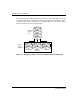
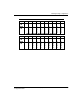
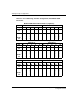
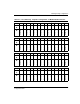
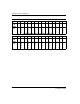
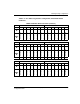
Table Of Contents
- HSG80 ACS Solution Software Version 8.7 for Compaq Tru64 UNIX Installation and Configuration Guide
- About this Guide
- 1- Planning a Subsystem
- Defining Subsystems
- What is Failover Mode?
- Selecting a Cache Mode
- Enabling Mirrored Caching
- What is the Command Console LUN?
- Determining Connections
- Assigning Unit Numbers
- What is Selective Storage Presentation?
- 2- Planning Storage Configurations
- Where to Start
- Determining Storage Requirements
- Configuration Rules for the Controller
- Addressing Conventions for Device PTL
- Choosing a Container Type
- Creating a Storageset Profile
- Planning Considerations for Storageset
- Changing Characteristics through Switches
- Specifying Storageset and Partition Switches
- Specifying Initialization Switches
- Specifying Unit Switches
- Creating Storage Maps
- 3- Preparing the Host System
- Installing RAID Array Storage System
- Making a Physical Connection
- Preparing LUNs for Access by Tru64 UNIX FileSystem
- DECsafe Available Server Environment (ASE)
- HSG80 Units and Tru64 UNIX Utilities
- Solution Software Upgrade Procedures
- New Features, ACS 8.7 for Tru64
- 4- Installing and Configuring HSG Agent
- 5- FC Configuration Procedures
- Establishing a Local Connection
- Setting Up a Single Controller
- Setting Up a Controller Pair
- Configuring Devices
- Configuring Storage Containers
- Assigning Unit Numbers and Unit Qualifiers
- Configuration Options
- Verifying Storage Configuration from Host
- 6- Using CLI for Configuration
- 7- Backing Up, Cloning, and Moving Data
- A- Subsystem Profile Templates
- Storageset Profile
- Storage Map Template 1 for the BA370 Enclosure
- Storage Map Template 2 for the second BA370 Enclosure
- Storage Map Template 3 for the third BA370 Enclosure
- Storage Map Template 4 for the Model 4214R Disk Enclosure
- Storage Map Template 5 for the Model 4254 Disk Enclosure
- Storage Map Template 6 for the Model 4310R Disk Enclosure
- Storage Map Template 7 for the Model 4350R Disk Enclosure
- Storage Map Template 8 for the Model 4314R Disk Enclosure
- Storage Map Template 9 for the Model 4354R Disk Enclosure
- B- Installing, Configuring, and Removing the Client
- C- SWCC Agent in TruCluster Environment
- SWCC Overview
- Running the SWCC Agent on a V4.0G Cluster
- Running the SWCC Agent under ASE Services
- Running the SWCC Agent on a V5.x Cluster
- Problems with Running the Agent on Multiple Clusters
- Configure the Controller
- Use Multiple-Bus Failover Mode
- Verify That the HSG80/HSG60 Unit Offsets Are Zero
- Install and Run the Agent on One Cluster Member
- Example of Installing the Agent on a Cluster Member
- Create the CAA Action Script
- Create the CAA Resource
- Glossary
- Index

Planning Storage Configurations
2–7HSG80 ACS Solution Software Version 8.7 for Compaq Tru64 UNIX Installation and
Configuration Guide
2–7
Examples - Model 2200 Storage Maps, PTL Addressing
The Model 2200 controller enclosure can be combined with the following:
• Model 4214R disk enclosure — Ultra2 SCSI with 14 drive bays, single-bus I/O
module.
• Model 4254 disk enclosure — Ultra2 SCSI with 14 drive bays, dual-bus I/O
module.
NOTE: The Model 4214R uses the same storage maps as the Model 4314R, and the Model
4254 uses the same storage maps as the Model 4354R disk enclosures.
• Model 4310R disk enclosure — Ultra3 SCSI with 10 drive bays, single-bus I/O
module. Table 2–1 shows the addresses for each device in a six-shelf, single-bus
configuration. A maximum of six Model 4310R disk enclosures can be used with
each Model 2200 controller enclosure.
NOTE: The storage map for the Model 4310R reflects the disk enclosure’s physical location in
the rack. Disk enclosures 6, 5, and 4 are stacked above the controller enclosure, and disk
enclosures 1, 2, and 3 are stacked below the controller enclosure.
• Model 4350R disk enclosure — Ultra3 SCSI with 10 drive bays, single-bus I/O
module. Table 2–2 shows the addresses for each device in a three-shelf, single-bus
configuration. A maximum of three Model 4350R disk enclosures can be used
with each Model 2200 controller enclosure.
• Model 4314R disk enclosure — Ultra3 SCSI with 14 drive bays, single-bus I/O
module. Table 2–3 shows the addresses for each device in a six-shelf, single-bus
configuration. A maximum of six Model 4314R disk enclosures can be used with
each Model 2200 controller enclosure.
NOTE: The storage map for the Model 4314R reflects the disk enclosure’s physical location in
the rack. Disk enclosures 6, 5, and 4 are stacked above the controller enclosure, and disk
enclosures 1, 2, and 3 are stacked below the controller enclosure.
• Model 4354R disk enclosure — Ultra3 SCSI with 14 drive bays, dual-bus I/O
module. Table 2–4 shows the addresses for each device in a three-shelf, dual-bus
configuration. A maximum of three Model 4354R disk enclosures can be used
with each Model 2200 controller enclosure.
NOTE: Appendix A contains storageset profiles you can copy and use to create your own
system profiles. It also contains an enclosure template you can use to help you keep track of the
location of devices and storagesets in your shelves.