
HSG80 ACS Solution Software Version 8.7 for Compaq Tru64 UNIX Installation and Configuration Guide
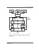

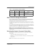

Table Of Contents
- HSG80 ACS Solution Software Version 8.7 for Compaq Tru64 UNIX Installation and Configuration Guide
- About this Guide
- 1- Planning a Subsystem
- Defining Subsystems
- What is Failover Mode?
- Selecting a Cache Mode
- Enabling Mirrored Caching
- What is the Command Console LUN?
- Determining Connections
- Assigning Unit Numbers
- What is Selective Storage Presentation?
- 2- Planning Storage Configurations
- Where to Start
- Determining Storage Requirements
- Configuration Rules for the Controller
- Addressing Conventions for Device PTL
- Choosing a Container Type
- Creating a Storageset Profile
- Planning Considerations for Storageset
- Changing Characteristics through Switches
- Specifying Storageset and Partition Switches
- Specifying Initialization Switches
- Specifying Unit Switches
- Creating Storage Maps
- 3- Preparing the Host System
- Installing RAID Array Storage System
- Making a Physical Connection
- Preparing LUNs for Access by Tru64 UNIX FileSystem
- DECsafe Available Server Environment (ASE)
- HSG80 Units and Tru64 UNIX Utilities
- Solution Software Upgrade Procedures
- New Features, ACS 8.7 for Tru64
- 4- Installing and Configuring HSG Agent
- 5- FC Configuration Procedures
- Establishing a Local Connection
- Setting Up a Single Controller
- Setting Up a Controller Pair
- Configuring Devices
- Configuring Storage Containers
- Assigning Unit Numbers and Unit Qualifiers
- Configuration Options
- Verifying Storage Configuration from Host
- 6- Using CLI for Configuration
- 7- Backing Up, Cloning, and Moving Data
- A- Subsystem Profile Templates
- Storageset Profile
- Storage Map Template 1 for the BA370 Enclosure
- Storage Map Template 2 for the second BA370 Enclosure
- Storage Map Template 3 for the third BA370 Enclosure
- Storage Map Template 4 for the Model 4214R Disk Enclosure
- Storage Map Template 5 for the Model 4254 Disk Enclosure
- Storage Map Template 6 for the Model 4310R Disk Enclosure
- Storage Map Template 7 for the Model 4350R Disk Enclosure
- Storage Map Template 8 for the Model 4314R Disk Enclosure
- Storage Map Template 9 for the Model 4354R Disk Enclosure
- B- Installing, Configuring, and Removing the Client
- C- SWCC Agent in TruCluster Environment
- SWCC Overview
- Running the SWCC Agent on a V4.0G Cluster
- Running the SWCC Agent under ASE Services
- Running the SWCC Agent on a V5.x Cluster
- Problems with Running the Agent on Multiple Clusters
- Configure the Controller
- Use Multiple-Bus Failover Mode
- Verify That the HSG80/HSG60 Unit Offsets Are Zero
- Install and Run the Agent on One Cluster Member
- Example of Installing the Agent on a Cluster Member
- Create the CAA Action Script
- Create the CAA Resource
- Glossary
- Index

Planning a Subsystem
1–17HSG80 ACS Solution Software Version 8.7 for Compaq Tru64 UNIX Installation and
Configuration Guide
1–17
•The UNIT_OFFSET switch in the ADD CONNECTIONS (or SET connections) commands
• The controller port to which the connection is attached
•The SCSI_VERSION switch of the SET THIS_CONTROLLER/OTHER_CONTROLLER command
The considerations for assigning unit numbers are discussed in the following sections.
Matching Units to Host Connections in Transparent Failover
Mode
In transparent failover mode, the ADD UNIT command creates a unit for host connection
to access and assigns it to either port 1 or port 2 of both controllers.
Unit numbers are assigned to ports as follows:
•0−99 are assigned to host port 1 of both controllers.
•100−199 are assigned to host port 2 of both controllers.
For example, unit D2 is on port 1, and unit D102 is available through port 2.
The LUN number that a host connection assigns to a unit is a function of the
UNIT_OFFSET switch of the
ADD (or SET) CONNECTIONS command. The relationship of
offset, LUN number, and unit number is shown in the following equation:
LUN number = unit number – offset
Where...
— LUN number is relative to the host (what the host sees the unit as)
— Unit number is relative to the controller (what the controller sees the unit as)
If no value is specified for offset, then connections on port 1 have a default offset of 0
and connections on port 2 have a default offset of 100.
For example, if all host connections use the default offset values, unit D2 will be
presented to a port 1 host connection as LUN 2 (unit number of 2 minus offset of 0).
Unit D102 will be presented to a port 2 host connection as LUN 2 (unit number of
D102 minus offset of 100).
Figure 1–12 shows how units are presented as different LUNs, depending on the offset
of the host. In this illustration, host connection 1 and host connection 2 would need to
be on host port 1; host connection 3 would need to be on host port 2.