-
-
About This Manual P/N:01.54.458126 MPN: 01.54.458126010 Release Date: March, 2019 © Copyright EDAN INSTRUMENTS, INC. 2019 This User Manual applies to 1.0X releases for Acclarix LX9 series Diagnostic Ultrasound Systems including Acclarix LX9, Acclarix LX9 Exp, Acclarix LX9 Super, Acclarix LX85 and Acclarix LX88. See Appendix A.9 for the difference between these models. This User Manual Basic Volume together with the User Manual Advanced Volume (P/N: 01.54.
-
Contents 1 Introduction .................................................................................................................................. 1 1.1 Intended Use/ Indications for Use .............................................................................................. 1 1.2 Contra-indications ...................................................................................................................... 1 1.3 Device Description ....................................................
-
5.3.2. PW Image Optimization .................................................................................................... 48 5.3.3. HPRF ............................................................................................................................... 51 5.4 CW Mode ................................................................................................................................. 51 5.4.1. Using CW Mode ......................................................................
-
6.3 Transducer Cleaning and Disinfecting ...................................................................................... 84 6.3.1. Cleaning ........................................................................................................................... 84 6.3.2. Disinfection ....................................................................................................................... 84 6.3.3. Sterilization ..........................................................................
-
8.3.2. Report ............................................................................................................................ 139 8.4 Measurement Accuracy .......................................................................................................... 140 9 Exam Data Management .......................................................................................................... 141 9.1 Storing Images ...............................................................................
-
12.3 Storage ................................................................................................................................. 174 13 Troubleshooting and Maintenance ......................................................................................... 175 13.1 Daily Checklist ...................................................................................................................... 175 13.2 Troubleshooting .......................................................................
-
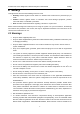
Acclarix LX9 Series Diagnostic Ultrasound System User Manual Introduction 1 Introduction 1.1 Intended Use/ Indications for Use The Acclarix LX9 series Diagnostic Ultrasound System is intended for use by a qualified physician or allied health professional for ultrasound evaluations in hospitals and clinics.
-
Acclarix LX9 Series Diagnostic Ultrasound System User Manual Safety 2 Safety Throughout this document the following terms are used: Warning: Advises against certain actions or situations that could result in personal injury or death. Caution: Advises against actions or situations that could damage equipment, produce inaccurate data, or invalidate a procedure. Note: Provides useful information regarding a function or a procedure. Please read all warnings and cautions prior to using the system.
-
Acclarix LX9 Series Diagnostic Ultrasound System User Manual Safety Transmissible Spongiform Encephalopathies. The transducers for your system cannot be decontaminated using a heat process. Contact with natural rubber latex may lead to a severe anaphylactic reaction in persons sensitive to the natural latex protein, Sensitive users and patients must avoid contact with these items.
-
Acclarix LX9 Series Diagnostic Ultrasound System User Manual Safety Use a sterile needle with each use. The system may be interfered with by other equipment, even if that other equipment complies with CISPR EMISSION requirements. The system cannot be used together with high-frequency surgical equipment. Remove the battery from the device when the device is not used for a long time.
-
Acclarix LX9 Series Diagnostic Ultrasound System User Manual Safety without compromising the image quality. Do not use in the presence of a flammable anesthetic. The system generates radio frequency energy, which may cause interference with other devices in the vicinity. If interference is suspected, try re-orienting or relocating the equipment. The use of electrosurgical units or other devices that generate radio frequency interference may cause image distortion or other malfunctions.
-
Acclarix LX9 Series Diagnostic Ultrasound System User Manual Safety To ensure safety, two persons are required to move the device across slopes. Transducer Cautions Do not use disinfection agents beyond their expiration date. Do not use sterile sheaths beyond their expiration date. Inspect the transducer connector, cable, and head periodically. Do not use if there is evidence of excessive wear or damage.
-
Acclarix LX9 Series Diagnostic Ultrasound System User Manual Safety - Reorient or relocate the receiving antenna. - Increase the separation between the equipment and receiver. - Connect the equipment into an outlet on a circuit different from that to which the receiver is connected. - Consult the dealer or an experienced radio/TV technician for help. This equipment complies with FCC radiation exposure limits set forth for an uncontrolled environment.
-
Acclarix LX9 Series Diagnostic Ultrasound System User Manual Safety 13 General Symbol for Recovery / Recyclable 14 Caution: Federal (U.S.) law restricts this device to sale by or on the order of a physician. 15 IPX7 No harm for short time immersion 16 Type BF Applied Part 17 Transducer connector 18 Pencil Transducer connector (reserved) 19 ECG connector 21 Transducer lock 22 Transducer unlock 23 Equipotential grounding 24 Network port 25 Trademark 26 Video Output port 27 USB 2.
-
Acclarix LX9 Series Diagnostic Ultrasound System User Manual 31 Audio output 32 AC power indicator 33 Batter charging indicator 34 Up/Down button, to move the control panel up or down 35 Non-ionizing electromagnetic radiation. 36 FCC ID:SMQLX9EDAN Safety Federal Communications Commission: FCC ID:SMQLX9EDAN 37 Type CF Applied Part with Defibrillation-proof protection 38 Non-sterile. Indicates a medical that has not been subjected to a sterilization process.
-
Acclarix LX9 Series Diagnostic Ultrasound System User Manual The following labels are used on the wooden packaging: No. Symbol Definition 1 This way up 2 Fragile, handle with care 3 Keep dry 4 Stacking limit by number 5 Do Not Roll. 6 General Symbol for Recovery / Recyclable 7 Tilt monitored equipment. NOTE: The user manual is printed in black and white.
-
Acclarix LX9 Series Diagnostic Ultrasound System User Manual Getting Started 3 Getting Started 3.
-
Acclarix LX9 Series Diagnostic Ultrasound System User Manual Two batteries Wifi module ECG module Getting Started Supported Peripheral Accessories: The recommended printers are listed as follows: Printer Type Printer Model Interface SONY UP-25MD S-Video SONY UP-D25MD USB SONY UP-X898MD USB HP Officejet Pro 251dw USB HP LaserJet Pro 200 color M251n USB HP LaserJet CP1525n Color USB HP Deskjet Ink Advantage 2010 USB HP Deskjet 1010 USB HP Deskjet 1510 USB HP LaserJet 400
-
Acclarix LX9 Series Diagnostic Ultrasound System User Manual Getting Started WARNING Only the recommended printers listed above are verified by EDAN. Therefore, it is suggested to only use these printers. Use of other printers should comply with IEC 60950 or IEC 60601-1. Edan is not responsible for the accuracy of other printers. Recommended DVD drives: LITEON 3.2 System Overview 3.2.1.
-
Acclarix LX9 Series Diagnostic Ultrasound System User Manual No. Description No.
-
Acclarix LX9 Series Diagnostic Ultrasound System User Manual Getting Started 1 3 2 5 4 6 Figure 3-3 Rear View No. 1 Description No. Coupling Gel Holder/ Gel Warmer(Optional) Description 2 I/O Ports 3 Video Printer/DVD Drive(Optional) 4 Air Switch 5 Equipotential Terminal 6 AC Power Socket Table 3-4 Rear View Description CAUTION 1. To facilitate the disconnection from power supply, please do not cover the AC power socket with any object.
-
Acclarix LX9 Series Diagnostic Ultrasound System User Manual Getting Started Equipotential Connection The equipotential terminal is used for balancing the protective earth potentials between the ultrasound system and other electrical devices. Perform the equipotential connection as the following illustration. Equipotential terminal Rear panel Potential equalization conductor Equipotential terminal Another device WARNING 1.
-
Acclarix LX9 Series Diagnostic Ultrasound System User Manual Getting Started Caution 1. The resolution of the external display which connects to DVI port or HDMI port should be 1080P, otherwise the display will be abnormal. 3.2.2. Control Panel Figure 3-6 Control Panel No. Key Name Description Press to power on/off the system. 1. : AC power supply indicator. It illuminates in green when the system is connected to AC power supply. Power Switch : Battery charging indicator.
-
Acclarix LX9 Series Diagnostic Ultrasound System User Manual 6. Report 7. F1 Getting Started Press to display the report page. User-defined button. See section 11.1.1 for configuring the user-defined button. 8. F2 Steer The Steer knob control is only available for linear transducers. It can steer B-mode image, Color ROI, PW sample line, etc. Specific operations thereof are described throughout the user manual. 10. Angle Adjusts the angle of comment, body marks, needle, M sample line, etc.
-
Acclarix LX9 Series Diagnostic Ultrasound System User Manual 17. PW Getting Started Press to get the sample line. Use the trackball to adjust the position of the sample line. Press it again or press key to display the Doppler strip. Rotate this knob to adjust the gain in PW Mode. In 3D/4D mode, rotating it can rotate the image by the X-axis of the activated window. Press to get the sample line. Use the trackball to adjust the position of the sample line.
-
Acclarix LX9 Series Diagnostic Ultrasound System User Manual Getting Started 26. Caliper Invokes generic measurements. See section 8.1 for details. 27. Measure Invokes application measurements. See section 8.2 for details. Trackball Keys Two trackball keys provide a wide variety of functions depending on the system state (e.g., selects a start or end point of a measurement, selects menu items on the screen, etc). For the convenience of introduction, we call them throughout this user manual.
-
Acclarix LX9 Series Diagnostic Ultrasound System User Manual Getting Started In B mode, the Auto push button automatically updates the Overall Gain and TGC. In PW mode, the Auto push button automatically updates the PW gain, DR, baseline and scale. 36. In Color mode, this Auto push button automatically updates the gain and scale. Auto Each single press of the button renews the automatic optimization.
-
Acclarix LX9 Series Diagnostic Ultrasound System User Manual Getting Started ② Image Field The ultrasound image appears in the Image field, under the Information field. The Image field also contains information typically associated with the image, such as depth, TGC, maps, image parameters, MI and TI. ③ Measurements Display Field The left side of the screen displays available generic and application measurement items for current exam preset.
-
Acclarix LX9 Series Diagnostic Ultrasound System User Manual Getting Started Wi-Fi function is enabled, but no WI-FI network is connected. No WI-FI icon will be displayed when Wi-Fi function is disabled in Connectivity setup. Wi-Fi network is connected. 4 Wi-Fi icon Clicking on this icon shows a list of available Wi-Fi networks. Selecting an available network displays a dialog box for entering password.
-
Acclarix LX9 Series Diagnostic Ultrasound System User Manual Getting Started Battery 60%-80% charged. Battery 40%-60% charged. Battery low, symbol in red. Battery removed, outline in red. Battery charging. Symbol in grey: DVD device is connected. 8 DVD icon Symbol in green: DVD device is connected, disc is inserted and data transmission is available. 3.2.1. Touch Screen The Touch Screen contains controls that vary depending on the active imaging mode or function.
-
Acclarix LX9 Series Diagnostic Ultrasound System User Manual Getting Started immediately performs an action (like “Auto”) D. Radio Buttons: A collection of buttons where only one is active at any time. Activating one will de-activate all others. E. Folder: Controls can be grouped together into a folder. Press on the folder to open it and access any of the controls within it. F. Pages: When a tab has multiple pages of controls each page is represented by a dot at the top of the page.
-
Acclarix LX9 Series Diagnostic Ultrasound System User Manual Getting Started 3.2.4. Trackball The trackball operation is easy and convenient. It can achieve the following functions: Move the measurement cursor during measurement. Move the comment cursor in the comment status. Move the M Mark in the B+M mode. Move the scan area of Color mode, increase or decrease the size of scan area of Color mode. Move the sample line in the PW/CW mode.
-
Acclarix LX9 Series Diagnostic Ultrasound System User Manual Getting Started 3.3 System Preparation 3.3.1. Battery Use The system may come with two lithium-ion batteries depending on your order. The fully charged batteries together can run the system for approximately 1.5 hours, depending on use. The batteries are automatically charged when the system is plugged in. CAUTION 1.
-
Acclarix LX9 Series Diagnostic Ultrasound System User Manual Getting Started 4. To fix the battery, move the battery holder to the middle position (see the figure below). 5. Close the battery door and secure it. WARNING 1. When the battery capacity is ≤20%, the battery status icon turns red. 2. When the battery capacity is ≤10%, the system displays a prompt “Low Battery. Please plug in the adapter to ensure uninterrupted use." To remove the battery: 1.
-
Acclarix LX9 Series Diagnostic Ultrasound System User Manual 4. Getting Started Close the battery door and secure it. 3.3.2. AC Power Use When using AC power, position the system so that it is easy to disconnect it from AC power supply. To connect AC power: 1. Connect the AC power cord to the power socket on the system(see figure 3-3). 2. Connect the AC power cord to a hospital-grade power outlet. 3. Toggle the Air Switch beside the power socket to "ON" position. 4.
-
Acclarix LX9 Series Diagnostic Ultrasound System User Manual 4. 5. Getting Started Ensure the transducer is connected firmly and properly. This is to avoid bad contact between the transducer and transducer socket. Ensure that the system is shut down, or the image is frozen, before connecting and disconnecting transducers. 3.3.4. Powering on/ off Please review and follow the steps described in the Section 13.1.Daily Checklist prior to powering on the system. To power on 1. Connect the AC power supply.
-
Acclarix LX9 Series Diagnostic Ultrasound System User Manual Getting Started 2. Select User from the confirmation dialog box. A login information dialog box will be displayed providing access to change user. 3. Select Change User and this brings up the system login dialog box. 4. Select another user from the User Name drop-down list and then enter password to login. To power off 1. Press the Power on/off key on the top left of control panel and the system displays a confirmation dialog box. 2.
-
Acclarix LX9 Series Diagnostic Ultrasound System User Manual Exam Operation 4 Exam Operation 4.1 How to Start an Exam 1. Press the key and enter in patient information, or select a scheduled patient from the modality worklist. If there is no previous exam, pressing the key will bring you directly to the Patient Information Page (see figure 4-2 below).
-
Acclarix LX9 Series Diagnostic Ultrasound System User Manual Exam Operation Figure 4-2 Example of Transducer Touch Screen 4.2 How to End an Exam There are two ways to end an exam: Pressing the key, as described above, and then selecting the New Exam. This both ends the exam and displays the Patient Information Page for the next exam. Pressing the key, as described above, and then selecting the End Exam.
-
Acclarix LX9 Series Diagnostic Ultrasound System User Manual Exam Operation Figure 4-2 Patient Information Page The top three lines are for entering the patient last name, first name, ID, exam accession number, and DOB (Date-of-Birth) or age. If date of birth is entered, the age is automatically calculated. Note: By default, the patient name has two fields: family name and given name. It can be configured to be one field in the Patient Setup screen (See section 11.1.2 for detail).
-
Acclarix LX9 Series Diagnostic Ultrasound System User Manual Exam Operation calculated. An A GA more than 42W6D days is considered invalid. Fetus: Enter 1 up to 4 for multiple gestations. G/P/A: G stands for Gravida, P stands for Para and A stands for Aborta. Enter values for each in the fields separated by slashes. Study Description: enter the study description. Height: Enter the patient‟s height. The units can be set in the Patient section of Setup. Weight: Enter the patient‟s weight.
-
Acclarix LX9 Series Diagnostic Ultrasound System User Manual Exam Operation Figure 4-4 Modality Worklist Display The worklist is displayed at the left side of the Patient Information Page in two columns labeled patient name and patient ID. Clicking on the header of each column will sort the list for the corresponding column. The worklist shows all scheduled ultrasound exams within the date-range specified in the Connectivity Utility (See 11.2.2).
-
Acclarix LX9 Series Diagnostic Ultrasound System User Manual Imaging 5 Imaging 5.1 B-mode 5.1.1. Using B-mode 1. Press on the console to enter B mode. 2. Perform the image scanning. 3. Adjust Image parameters to optimize the image. 5.1.2. B-mode Image Optimization The following touch controls can be used to optimize the B-mode image. Name Control Description Dynamic Range The Dynamic Range, or log compression, adjusts how echo intensities are converted to brightness.
-
Acclarix LX9 Series Diagnostic Ultrasound System User Manual Imaging Spatial Compounding Spatial Compounding combines images fired from multiple angles to reduce speckle, reduce shadow artifacts, and enhance contrast. Spatial compounding is an on/off control. Focus Number Focus Number adjusts the number of foci is displayed. As the number of foci increases, image uniformity across depth will increase, but the frame rate will decrease.
-
Acclarix LX9 Series Diagnostic Ultrasound System User Manual Imaging Steer The Steer control is only available for linear transducers and steers the B-mode image left or right, without moving the transducer. This function can be particularly useful when visualizing needles or other objects that are enhanced by a perpendicular beam. Steer is not available if Spatial Compounding, Extended FOV or Panorama is turned on. Panorama The Panorama control invokes the Panorama function. See section 5.
-
Acclarix LX9 Series Diagnostic Ultrasound System User Manual Imaging Needle Press to invoke the touch screen for Needle Enhancement Visualization and Needle Biopsy Guide functions. See section 6.4 and 6.5 for more information. Center Line Press to activate the Center Line function. Refer to section 6.6 for details. Press to invoke extended field of view function. Only available for linear transducers.
-
Acclarix LX9 Series Diagnostic Ultrasound System User Manual Imaging 5.2 Color Mode 5.2.1. Color Mode Variants The system supports 3 types of Color Doppler imaging: Color (Color Doppler): This is velocity Color Doppler that shows direction and velocity of flow. Different colors represent different velocities and positive flow has different colors than negative flow. PDI (Power Doppler Imaging): PDI shows the power, or intensity, of the Doppler signal.
-
Acclarix LX9 Series Diagnostic Ultrasound System User Manual Imaging Invert Normally, signals above the baseline are positive velocities (moving toward the transducer). However, when Invert is pressed then negative velocities are above the baseline. Invert does not affect the baseline position. Invert is not available in PDI mode. Baseline The Baseline control adjusts the Color baseline. Upward presses move the baseline up on the scale and downward presses move the baseline down.
-
Acclarix LX9 Series Diagnostic Ultrasound System User Manual Imaging Frequency Frequency determines the transmit frequency used by color Doppler. Upward presses increase the frequency. Downward presses decrease the frequency. Steer This control is only available for linear transducers. It steers the Color ROI box angle left or right. Image Type Color Doppler supports image presets for Low Flow, Medium Flow, and High Flow. Dual Live To activate split screen with simultaneous live B/Color and live B.
-
Acclarix LX9 Series Diagnostic Ultrasound System User Manual Imaging 5.3 PW Mode 5.3.1. Using PW Mode 1. Perform the image scanning to get a good image in B mode or B+Color(DPI/DPDI) mode; 2. Press on the console to display sample line; 3. Use the trackball and touch controls to adjust the position of the sample line and the size and angle of the sample gate; 4. Press on the console to enter B+PW or B+Color(PDI/DPDI)+PW mode and display Doppler strip. 5.
-
Acclarix LX9 Series Diagnostic Ultrasound System User Manual Imaging Filter The Filter control removes excessive noise from movement of vessel walls. Options of Low, Med and High are available. Higher wall filter level will suppress more strong single of the vessel walls, but low flow signal will be missing. Colorize Switches between grayscale and colorized (pseudo-color) postprocessing maps.
-
Acclarix LX9 Series Diagnostic Ultrasound System User Manual Duplex (Triplex) Imaging This determines if the strip mode and reference image are imaging simultaneously or not. In Duplex mode, either the Doppler strip or the reference image is updated continuously. In Triplex mode, both the Doppler strip and reference image are updated simultaneously. Image Type Spectral Doppler supports image presets for Low Flow, Medium Flow and High Flow.
-
Acclarix LX9 Series Diagnostic Ultrasound System User Manual Imaging 5.3.3. HPRF Conventional PW Doppler scales are limited by the Nyquist limit. High Pulse Repetition Frequency (HPRF) allows the system to exceed the Nyquist limit by having multiple Doppler pulses in the body at the same time. In HPRF imaging, multiple Doppler gates are displayed since the multiple Doppler pulses could be giving information from different depths.
-
Acclarix LX9 Series Diagnostic Ultrasound System User Manual Imaging Invert Normally, signals above the baseline are positive velocities (moving toward the transducer). However, when Invert is pressed then negative velocities are above the baseline. Invert does not affect the baseline position. Image Type Strip Doppler supports image presets for Low Flow, Medium Flow, and High Flow. Angle Correct Adjust the Doppler scale to account for the angle between the Doppler cursor and the blood flow.
-
Acclarix LX9 Series Diagnostic Ultrasound System User Manual Imaging Sweep Speed Sweep adjusts the sweep speed of the Doppler strip. Options of Slow, Low, Med, High and Fast are available. Upward presses increase sweep speed. Downward presses decrease sweep speed. Strip Size Changes the relative size of the Doppler strip compared to the reference image. Full, Large, Med. and Small are available. Volume Volume adjusts the audio volume of the Doppler strip.
-
Acclarix LX9 Series Diagnostic Ultrasound System User Manual Gray Map Tint Imaging Adjusts the current postprocessing, either grayscale or tinted. Dynamic Range The Dynamic Range, or log compression, adjusts how echo intensities are converted to brightness. A high dynamic range will display more shades of gray, while a low dynamic range will display fewer shades of gray and a more contrasty M-mode display. Focus Position The focus position set in B-mode applies to M-mode as well.
-
Acclarix LX9 Series Diagnostic Ultrasound System User Manual Imaging Acoustic power Adjusts the acoustic output power of the activated transducer. It is only available in live imaging. Higher acoustic power numbers correspond to increased sensitivity and penetration in the image, but ALARA principle should be followed in actual situations. Anatomic M Invokes Anatomic M mode. Table 5-5 M-Mode Touch Screen Controls 5.
-
Acclarix LX9 Series Diagnostic Ultrasound System User Manual Imaging 5.7 Color M Mode Color M mode superimposes color encoded information on M mode strip to indicate the direction, velocity and timing of cardiac flow and tissue movements. The direction of cardiac tissue movements can be identified by color changes. The Color M mode includes Color Flow M mode and Color Tissue M mode. 5.7.1. Using Color M Mode 1.
-
Acclarix LX9 Series Diagnostic Ultrasound System User Manual Imaging 5.8 TDI Mode Tissue Doppler Imaging (TDI) mode shows information about low-velocity and high-amplitude tissue motion, usually used to evaluate cardiac tissue motion. Only Phased transducer supports TDI mode. There are two types of TDI modes available on this system: Color-TDI mode: shows the speed and direction of tissue motion on real-time Color image. PW-TDI mode: shows the speed of tissue motion on Strip Doppler image. 5.8.1.
-
Acclarix LX9 Series Diagnostic Ultrasound System User Manual Imaging 5.9 3D/4D Mode 3D/4D mode is only available on a Wobble transducer. There are two ways to activate pre-3D or Pre-4D mode: 1. Press the <3D> or <4D> on the console. 2. Press the 3D or 4D button on the touch screen in B-mode. 5.9.1. Pre-3D/Pre-4D The Pre-3D and Pre-4D mode supports defining the 3D and 4D acquisition location and settings. Figure 5-2 shows an example of the pre-3D image.
-
Acclarix LX9 Series Diagnostic Ultrasound System User Manual Imaging Surface/ Skeleton These two radio buttons determine if the acquisition is optimized for looking at Skeleton or Surface. 3D Displayed in Pre-4D. Press to switch to Pre-3D. 4D Displayed in Pre-3D. Press to switch to Pre-4D. Start Start an acquisition. Exit Exit 3D/4D Table 5-7 Pre-3D Touch Screen 5.9.2.
-
Acclarix LX9 Series Diagnostic Ultrasound System User Manual Imaging 5.9.3. 3D Image Review The system will enter to the 3D review status after finishing one sweep. Figure 5-3 3D Image Review There are two image modes: Volume imaging mode and multi-slice imaging mode. Figure 5-3 shows Volume Imaging Mode in quad screen with a Baby Face volume rendering. Quadrant A shows a slice through the data that mimics the original ultrasound image.
-
Acclarix LX9 Series Diagnostic Ultrasound System User Manual Imaging Single, Dual, Quad These three radio buttons switch the display to show 1, 2, or 4 images at once. Single shows the 3D image, dual shows the A slice and 3D image, Quad shows three MPR slices and 3D image. VOI Press to activate the function of adjusting VOI or clip plane. Use the trackball to adjust and press to switch between VOI and clip plane. Cut This is a folder of cut functions with various cut tools inside.
-
Acclarix LX9 Series Diagnostic Ultrasound System User Manual Imaging Contrast Adjust the contrast of 3D image. 3D Smooth MPR Smooth Adjust smoothness of A\B\C slices and 3D images. Higher filter levels create a smoother image. Upward presses increase the filter. Downward presses decrease the filter. Quick Rotation Four radio buttons used to quickly rotate the image. Available angles are: 0°/90°/180°/270°.
-
Acclarix LX9 Series Diagnostic Ultrasound System User Manual Imaging Image area and touch screen controls in multi-slice imaging mode: Figure 5-4 Multi-slice Imaging Mode In figure 5-5, the first image shows the basis slice, other images are orthogonal to the basis slice and parallel to each other. Lines on the basis slice indicate the locations of the parallel slices. If there are more slices than images then the un-displayed slices are shown with a dotted line.
-
Acclarix LX9 Series Diagnostic Ultrasound System User Manual Imaging Distance Adjust the distance between slices. Next When there are more slices than can be displayed at once this control cycles through the subset of slices displayed. Tint Select multi-slice tint. Smooth Adjust smoothness of A\B\C slices. Higher filter levels create a smoother image. Upward presses increase the filter. Downward presses decrease the filter. Table 5-9 Multi-slice Mode Touch Screen 5.9.4.
-
Acclarix LX9 Series Diagnostic Ultrasound System User Manual Imaging Figure 5-5 4D Volume Sweeping Image 5.9.6. 4D Cine During the process of 4D live volume imaging, press the button on the control panel to enter the 4D cine mode. A cine replay scroll bar appears below the images. Use the trackball to replay the images. For the selected frame, user can execute all operations that are available in 3D review status. Press again to return to the live image.
-
Acclarix LX9 Series Diagnostic Ultrasound System User Manual Imaging 5.9.7. Knobs and Buttons on Control Panel Knobs and buttons on control panel can also be used to make operation more convenient in 3D/4D mode. Name Control Description Rotation X Rotate this knob to rotate the basis slice by the X-axis of the activated window. Parallel slices change with the rotation operation. Rotation Y Rotate this knob to rotate the basis slice by the Y-axis of the activated window.
-
Acclarix LX9 Series Diagnostic Ultrasound System User Manual Imaging 5.10 Panorama Panorama constructs an extended field of view image as the user slides the transducer along its long axis. Panorama is available only with Linear and Convex transducers. This system also provides Color Panoramic imaging so that you can get color flow information on the panoramic image. Caution 1. The panoramic image is for reference only. Diagnosis must not be based on results achieved from panoramic image alone.
-
Acclarix LX9 Series Diagnostic Ultrasound System User Manual Imaging 5.11 Elastography Elastography imaging maps the elastic properties of soft tissue with different colors in a region of interest by estimating the strain before and after tissue distortion caused by external or internal forces. Only linear transducers support Elastography. Figure 5-8 Example of Strain Elastography Display 5.11.1. Using Elastography Mode To Use Elastography Mode: 1. Perform the scan in B mode and locate the lesion. 2.
-
Acclarix LX9 Series Diagnostic Ultrasound System User Manual 3. Imaging The Elastography image is for reference only. The image quality and measured results in Elastography mode always depend on the accuracy of the procedure performed. Any clinic diagnosis should be verified with other effective diagnosis methods. 5.11.2. Elastography Image Optimization The following touch controls can be used to optimize the Elastography image.
-
Acclarix LX9 Series Diagnostic Ultrasound System User Manual Imaging 5.12 Contrast Imaging Contrast Imaging is the application of ultrasound contrast agent to 2D Sonography. Injected contrast agents re-emit incident acoustic energy much more efficiently than the surrounding tissue, therefore, bringing enhanced imaging contrast between tissues. The main clinical uses of Contrast imaging include detecting and characterizing tumors and enhancing blood flow signals.
-
Acclarix LX9 Series Diagnostic Ultrasound System User Manual Imaging 5.12.1. Using Contrast Imaging 1. 2. 3. 4. 5. Invoke C5-1Q or C5-2Q transducer as the currently active transducer. Select ABD or Urology exam preset. Perform the 2D image scanning, and obtain the target image. Press Contrast on the touch screen and activate Contrast imaging mode. Adjust the acoustic power or optimize the Contrast image, if necessary, to obtain a good image. 6. 7.
-
Acclarix LX9 Series Diagnostic Ultrasound System User Manual Destroy Time Adjusts the time microbubbles. Frequency Frequency determines the transmit frequency used by Contrast Imaging mode. Upward presses increase the frequency. Downward presses decrease the frequency. Acoustic Power Adjusts the acoustic output power of the activated transducer. It is only available in live imaging.
-
Acclarix LX9 Series Diagnostic Ultrasound System User Manual Imaging Map The Gray Map adjusts the post processing map used on the Contrast image. In general, higher map numbers correspond to more contrast in the image. Cine Speed Adjusts the speed of playing cine loop. Time Intensity Curve Activates Time Intensity Curve displays. See section 5.11.3 for details. Exit Exits Contrast Imaging mode. Table 5-13 Touch Screen Controls of Contrast Imaging 5.12.3.
-
Acclarix LX9 Series Diagnostic Ultrasound System User Manual Imaging No. Name Description 1. Contrast cineloop window Displays contrast cineloop and ROIs. 2. Tissue cineloop window Displays tissue cineloop and ROIs. 3. ROIs The ROI indicates sampling position of the TIC. ROIs are color-coded, and up to 7 ROIs can be displayed. The TIC Analysis window displays: 4. Y axis represents intensity scale (dB). Frame marker, a white vertical line.
-
Acclarix LX9 Series Diagnostic Ultrasound System User Manual Exit Imaging Exits TIC Analysis. Basic TIC Analysis procedures 1. 2. 3. 4. 5. 6. 7. 8. Perform the scanning and inject Contrast agent. Freeze the image or select a range of images for analysis. Or, Select a desired cine loop from the stored images. Press TIC touch button to activate time intensity curve analysis. Place ROIs (region of interest) on one of these images, and time intensity curves are displayed below the image area.
-
Acclarix LX9 Series Diagnostic Ultrasound System User Manual Imaging 5.13 ECG The ultrasound system can be configured with an optional ECG module. The ECG module obtains ECG signals via ECG patient cable to display ECG waveform synchronously with the ultrasound image. The ECG signals can be used as time reference in cardiac exam for marking the systolic and end diastolic moments. WARNING 1. The ECG waveforms displayed on the main screen are not intended for ECG diagnosis and monitoring. 2.
-
Acclarix LX9 Series Diagnostic Ultrasound System User Manual Imaging 5.13.1. ECG Touch Screen Controls The following touchscreen controls impact the ECG function: Name Control Description ECG Displays or hides ECG waveforms and heart rate value on the main screen. Gain Adjusts the gain of ECG waveform. ECG Lead Selects the ECG lead from I, II and III lead as the ECG waveform source. AC Filter Selects the AC filter frequency according to the AC power you use. 50 Hz and 60 Hz are available.
-
Acclarix LX9 Series Diagnostic Ultrasound System User Manual Imaging Figure 5-11 3-lead Placement of AHA Standard 3. The image area displays real-time ECG waveform and heart rate value. There is a red mark on the ECG waveform indicating the temporal position of ultrasound image in relation to the ECG waveform. 4. Switch imaging modes and adjust relevant parameters to optimize the image. 5. Adjust ECG Gain and select ECG lead if necessary. 6. Freeze the image and review. 7. Exit ECG mode.
-
Acclarix LX9 Series Diagnostic Ultrasound System User Manual Transducers and Biopsy 6 Transducers and Biopsy 6.1 Transducer Model No.
-
Acclarix LX9 Series Diagnostic Ultrasound System User Manual Transducers and Biopsy Adult Cardiac Pediatric 9 P7-3Q Phased Array Abdominal Body Surface Pediatric Cardiac Neonatal Cephalic Abdominal Fetal / Obstetrics 10 C7-2XQ Convex Urology Body Surface Gynecology Musculoskeletal Fetal / Obstetrics Trans-vaginal 11 E10-3BQ Micro Convex Trans-rectal Intra-cavity Urology Gynecology Fetal / Obstetrics Trans-vaginal 12 E10-3HQ Micro Convex Trans-rectal Intra-cavity Urology Gynecology Feta
-
Acclarix LX9 Series Diagnostic Ultrasound System User Manual Transducers and Biopsy 6.2 Using Transducers Understanding a Transducer: Figure 6-1 takes L12-5Q transducer to show an example of a transducer. 1 2 3 5 4 6 7 Figure 6-1 Typical transducer No. Name Function 1 Transducer head Converts electrical signals to sound waves, and then converts received echoes back to electrical signals. The tip of the transducer is the acoustic lens. 2. Center mark 3.
-
Acclarix LX9 Series Diagnostic Ultrasound System User Manual Transducers and Biopsy Image Orientation Mark The image orientation marks on the display screen and on the transducer are shown as below. The side of orientation mark on the transducer corresponds to the side of orientation mark on the display screen. Ensure orientation marks on the display screen and transducer are on the same side prior to scanning.
-
Acclarix LX9 Series Diagnostic Ultrasound System User Manual Transducers and Biopsy Use of Transducer sheath CAUTION 1. Always wear gloves to perform the following steps. 2. To minimize disease transmission, legally marketed, sterile transducer sheath is required to use for intra-cavitary and intra-operative procedures. 3. Use a pyrogen-free transducer sheath for intra-operative procedures. 4. DO NOT use an expired transducer sheath.
-
Acclarix LX9 Series Diagnostic Ultrasound System User Manual Transducers and Biopsy 6.3 Transducer Cleaning and Disinfecting Transducers should be cleaned and/or disinfected as necessary or between use with a recommended cleanser or disinfectant. Disconnect the transducer from the system prior to cleaning and disinfecting. 6.3.1.
-
Acclarix LX9 Series Diagnostic Ultrasound System User Manual Contact normally sterile tissue Intra-operative Transducers and Biopsy Sterilization Immersion Note: LLD=Low-level Disinfection; HLD=High-level disinfection The validated disinfectants for transducer are: Disinfectants Disinfecting Intensity Disinfecting Method Ethanol (75%) LLD Spraying or wiping Isopropanol (70%) LLD Spraying or wiping Cidex OPA (0.55%) HLD Immersion Cidex Glutaraldehyde(2.
-
Acclarix LX9 Series Diagnostic Ultrasound System User Manual Transducers and Biopsy instructions provided by the disinfectant manufacturer for the concentration of the disinfection solution, method of dilution, method of disinfection, temperature and cautions during use. 5. Place the cleaned and dried transducer in contact with the disinfectant (refers to figure 6-3 for the contacting area) for the time specified by the disinfectant manufacturer.
-
Acclarix LX9 Series Diagnostic Ultrasound System User Manual Transducers and Biopsy 6. The immersion time should not exceed the time that is specified by the disinfectant manufacturer. 7. Patient contact area should be immersed into the solution while using the immersion method, but should not exceed the depth shown in figure 6-3. 6.3.3. Sterilization Intra-operative transducers must be sterilized after each exam. Sterilizing the transducers: 1. Disconnect the transducer from the system. 2.
-
Acclarix LX9 Series Diagnostic Ultrasound System User Manual Transducers and Biopsy 6.4 Needle Biopsy Guide NOTE: Use proper sterile technique at all times when performing a biopsy. Always follow these basic precautions: WARNING 1. Disinfect the needle guide kit before the first use and after each subsequent use. 2. Calibrate the needle guide kit (see section 6.4.3) under any of the following conditions: a) The first time that each bracket/transducer combination is used.
-
Acclarix LX9 Series Diagnostic Ultrasound System User Manual Transducers and Biopsy Structures: Locking Knob Clamp Angle Knob Tab Release Adjusting Knob Needle Guide Path Installation and Use Steps: 1. Place an appropriate amount of gel on transducer surface, and insert transducer into the sheath. 2. Loosen the locking knob to open the clamp of bracket. Attach the bracket to the transducer by aligning the locating markers on the bracket and the transducer.
-
Acclarix LX9 Series Diagnostic Ultrasound System User Manual 5. Transducers and Biopsy After biopsy, press the tab release to remove the needle, and loosen the locking knob to remove the bracket from the transducer. BGK-CR10UA Structures: Needle Guide Path Locking Knob Clamp Installation and Use Steps: 1. Place an appropriate amount of gel on transducer surface, and insert transducer into the sheath. 2. Loosen the locking knob to open the clamp of bracket.
-
Acclarix LX9 Series Diagnostic Ultrasound System User Manual 3. Transducers and Biopsy Properly secure the clamp of bracket with the locking knob. Ensure the backet is firmly attached, and then place the biopsy needle into the needle guide path. BGK-005/BGK-006 The installation steps for these brackets are the same. Here we take one bracket for illustration. Structures: Needle Guide Path Quick Release Clamp Installation and Use Steps: 1.
-
Acclarix LX9 Series Diagnostic Ultrasound System User Manual Transducers and Biopsy 3. Press the left and right side of the clamp as the figure below to attach the bracket to the transducer firmly. 4. Ensure the bracket is firmly attached, and then place the biopsy needle into the needle guide path. BGK-001 Structures: Installation and Use Steps: 1. Place an appropriate amount of gel on transducer surface, and insert transducer into the sheath.
-
Acclarix LX9 Series Diagnostic Ultrasound System User Manual Transducers and Biopsy 2. Loosen the locking knob to open the clamp bracket. Attach the bracket to the transducer by aligning the locating markers on the bracket and the transducer. Properly secure the clamp of bracket with the locking knob. 3. Install the disposable Needle Guide. a. b. Select appropriate disposable needle guide to achieve target depth from skin line: Specification Depth 21G(1.0cm) 0.8 - 1.2 cm 21G(1.5cm) 1.3 - 1.
-
Acclarix LX9 Series Diagnostic Ultrasound System User Manual Transducers and Biopsy 6.4.2. Activating Needle Guide Function To enable the needle guide function: 1. In the B mode imaging, press Needle button on touch screen, A needle touch screen UI is displayed, Press Enable button to active the Needle Guide function. 2. Press Double Line button to switch double line and single line as the Needle guide Line graphics. 3. Some needle guide brackets support multiple angles.
-
Acclarix LX9 Series Diagnostic Ultrasound System User Manual Transducers and Biopsy Figure 6-5 Needle Guide Calibration Touch Screen To calibrate the guide line 1. Assemble the needle guide bracket on the transducer, and use the transducer to image a water bath or needle guide phantom. 2. From the Needle function on the B-mode touch screen, press the Line paddle key to select a guide line. 3. Press the Calibration button on the touch screen to display the Angle and Position paddle button. 4.
-
Acclarix LX9 Series Diagnostic Ultrasound System User Manual Transducers and Biopsy Needle Visualization is invoked by pressing the Needle button on B-mode touch screen, and then the Enable button in the Needle Visualization section of the Needle touch screen. The following parameters can be adjusted when it is active. Enable: Enables or disables Needle Visualization. L/R: press to display the angle line on left side or right side of the image field.
-
Acclarix LX9 Series Diagnostic Ultrasound System User Manual Transducers and Biopsy 6.7.1. Cleaning 1. Wear sterile protective gloves to prevent infection. 2. Disconnect the needle guide bracket from the transducer after each use, and remove all visible residues from the needle guide bracket using a small and soft-bristled brush or other similar devices. Do the cleaning quickly before the needle guide bracket dries out. 3.
-
Acclarix LX9 Series Diagnostic Ultrasound System User Manual Features 7 Features 7.1 Comments The Comments function allows you add annotation to an image. The Comment function is invoked by pressing the hard key on the console. Figure 7-1 shows an example touch screen for the Comment function. The top portion of the screen shows comments that are pre-defined in pre-sets. See section 10 for details on how to configure these.
-
Acclarix LX9 Series Diagnostic Ultrasound System User Manual Features Adding comments You can add either pre-defined comments or use a keyboard. Adding comments using the keyboard 1. Invoke the Comment function. 2. Use the keyboard of the system or press the “Keyboard...” touch screen key to display a keyboard on the touch screen. 3. Move the cursor to the desired location and type the desired text. Adding comments using pre-defined comments 1. Invoke the Comment function 2.
-
Acclarix LX9 Series Diagnostic Ultrasound System User Manual Features 7.2 Body Mark Body Mark allows you add a body mark graphic to an image and indicate the location of the transducer using a transducer icon on that graphic. The Body Mark function is invoked by pressing the
hard key on the console. Figure 7-2 shows an example touch screen for Body Mark. The main portion of the screen shows a grid of body marks that are pre-defined in pre-sets.
-
Acclarix LX9 Series Diagnostic Ultrasound System User Manual Features Deleting a body mark: There are two ways of deleting a body mark graphic: Press Delete on the touch screen to delete the graphics on the image area. Press the hard key to delete all body marks, comments, and measurements. 7.3 Split Display 7.3.1. Dual Imaging Dual Imaging displays images side by side on the screen.
-
Acclarix LX9 Series Diagnostic Ultrasound System User Manual Features 7.4 Zoom The system supports two types of zoom: Pan Zoom: enlarges a full image and pans the enlarged image to view the desired area. Spot Zoom: focuses on processing the image of the selected area and enlarges the image with higher resolution. 7.4.1. Pan Zoom Pan Zoom is available on the live or frozen image in B mode and Color mode. Rotate the physical knob on console to zoom an image.
-
Acclarix LX9 Series Diagnostic Ultrasound System User Manual Measurements and Reports 8 Measurements and Reports The Measurement function lets you perform measurements on a live or frozen image. The Generic Measurement function is invoked by pressing the hard key on the console, and the Application Measurement function is invoked by pressing the hard key on the console. Generic Measurements: These are simple tools like Distance or Area.
-
Acclarix LX9 Series Diagnostic Ultrasound System User Manual Measurements and Reports Measurement main screen display is divided into three fields: Field 1: Displays measurement labels and attributes: The first line displays labels of Application Measurements and Generic Measurements. Clicking on each of them displays its associated measurement items.
-
Acclarix LX9 Series Diagnostic Ultrasound System User Manual No. Measurements and Reports Name Description A Measurement label Displays application and generic measurement labels. Pressing on any label will display its associated measurements on the touch screen. B Measurement groups Displays available measurement groups. Selecting one measurement group will show its associated measurement items below.
-
Acclarix LX9 Series Diagnostic Ultrasound System User Manual Measurements and Reports Understanding Measurement Result Window The measurement result window is displayed at the upper left corner of the image area by default. The following figure is an example of measurement result window. 1 2 Figure 8-3 Measurement Result Window In the measurement result window, the following operations are allowed. 1. Show/Hide measurement result window. 2.
-
Acclarix LX9 Series Diagnostic Ultrasound System User Manual Measurements and Reports 8.1 Generic Measurements Generic measurements is invoked by pressing key on the control panel. Each imaging mode supports different types of generic measurements. This chapter describes all the generic measurements supported in each imaging mode. 8.1.1. B-mode Generic Measurements The generic measurements supported in B-mode are listed in the table below. No. 1.
-
Acclarix LX9 Series Diagnostic Ultrasound System User Manual Measurements and Reports 8.1.1.2. Circumference/Area: Circumference/Area measurement can measure the circumference and area of a closed region. There are Ellipse, Trace and Spline methods. Ellipse Method: 1. Invoke the generic measurement function. 2. Select Circ/Area-> Area Ellipse. 3. Move the caliper to the start point. 4. Press the key to fix the start point. 5. Move the caliper and press the key to fix the end point.
-
Acclarix LX9 Series Diagnostic Ultrasound System User Manual Measurements and Reports 8.1.1.4. Volume Volume can be measured with 3 Distances or 1 Ellipse+1 distance method. 3-Distance Method: 1. Invoke the generic measurement function. 2. Select Volume-> Volume 3 Dist. 3. Move the caliper to the start point. 4. Press the key to fix the start point. 5. Move the caliper to the end point.
-
Acclarix LX9 Series Diagnostic Ultrasound System User Manual Measurements and Reports Spline Method: 1. Invoke the generic measurement function. 2. Select Circ/Area-> Stenosis% Spline 3. Perform two spline measurements following the Spline method in section 8.1.1.2 Circumference/Area measurement. 4. Then the Stenosis measurement result displays. 8.1.1.6. Elastography Ratio Elastography Ratio(Eratio) can measure the strain ratio between lesion and normal tissue. There are Ellipse and Trace methods.
-
Acclarix LX9 Series Diagnostic Ultrasound System User Manual Measurements and Reports 4. Press the key to fix the start point. 5. Move the caliper to the end point. Presses of the key will toggle between active calipers, allowing you to adjust the position of start point and end point. 6. Press the key to fix the end point and complete the measurement. 8.1.2.2. Slope The Slope measurement measures the distance and time between two points, and calculates the slope.
-
Acclarix LX9 Series Diagnostic Ultrasound System User Manual Measurements and Reports 8.1.3. Strip Doppler Generic Measurements The generic measurements supported in strip Doppler mode are listed in the table below. No. Measurement Group Measurement Item Remark PS ED RI PI PS,ED,RI,S/D 1. Generic Time HR Manual Trace Auto Trace Spline Trace Velocity Manual Trace Spline Trace 2. Generic Only available for Cardiac exam HR Time PGMax PGMean 3. Vessel 4.
-
Acclarix LX9 Series Diagnostic Ultrasound System User Manual Measurements and Reports PS/ED: measures the velocity at PS and ED points. 1. Invoke the generic measurement function. 2. Select Generic-> PS or ED. 3. Move the caliper to the PS or ED point on the strip. 4. Press the key to fix the point, and then PS or ED result displays. RI: measures the velocity at PS and ED points, and calculates RI result. 1. Invoke the generic measurement function. 2. Select Generic-> RI. 3.
-
Acclarix LX9 Series Diagnostic Ultrasound System User Manual Measurements and Reports Trace measurement is only available on a frozen strip. There are Manual Trace, Spline Trace and Auto Trace methods. Manual Trace Method: 1. Freeze the strip and invoke the generic measurement function. 2. Select Generic-> Manual Trace. 3. Move the caliper to the start point. 4. Press the key to fix the start point and start drawing the trace. 5. Moving the caliper to mark the trace outline.
-
Acclarix LX9 Series Diagnostic Ultrasound System User Manual Measurements and Reports 3. Move the caliper to the start point. 4. Press the key to fix the start point and start drawing the trace. 5. Moving the caliper to mark the trace outline. Presses of the key will toggle between active calipers, allowing you to adjust the positions of the PS or ED points in the trace. 6. Press the key to complete the trace.. 8.1.3.6.
-
Acclarix LX9 Series Diagnostic Ultrasound System User Manual Measurements and Reports 8.2 Application Measurements Application Measurements have a pre-defined meaning and can be entered into a report.
-
Acclarix LX9 Series Diagnostic Ultrasound System User Manual Measurements and Reports 8.2.1. Abdomen Measurements No. Measurement Group Measurement Item Description Method Section 1: B-mode Measurements 1.1 1.2 1.3 1.4 1.5 1.
-
Acclarix LX9 Series Diagnostic Ultrasound System User Manual No. Measurement Group Measurement Item Measurements and Reports Description 2.12 Splenic V Splenic Vein 2.13 SMV Superior Mesenteric Vein 2.14 IMV Inferior Mesenteric Vein Method 8.2.2. Gynecology Measurements No. Measurement Group Measurement Item Description Method Section 1: B-mode Measurements 1.1 1.2 1.3 1.4 1.5 1.
-
Acclarix LX9 Series Diagnostic Ultrasound System User Manual No. Measurement Group Measurement Item Measurements and Reports Description Method Spline Trace * The measurement method including 1 Distance, 2 Distances and 3 Distances can be configured in Measure Preset. See Section 10.4.1 for details. 8.2.3. Obstetrics Measurements Obstetric measurements are used to calculate the GA (Gestation Age), EDD (Estimated Delivery Date) and EFW (Estimated Fetus Weight).
-
Acclarix LX9 Series Diagnostic Ultrasound System User Manual No. 1.2 Measurement Group Measurement Item Measurements and Reports Description CRL Crown Rump Length BPD Biparietal Diameter FL Femur Length HUM Humerus Length Early Gest NT Nuchal Translucency Method Distance in B-mode generic measurements Distance in B-mode generic measurements; Auto(See 8.2.3.1) Distance in B-mode generic measurements; Auto(See section 8.2.3.
-
Acclarix LX9 Series Diagnostic Ultrasound System User Manual No. 1.7 1.
-
Acclarix LX9 Series Diagnostic Ultrasound System User Manual Measurements and Reports 8.2.3.1. Auto OB Measurement Auto OB is a method designed to measure BPD, HC, HUM and FL automatically. To use Auto OB measurement: 1. Select OB exam preset and perform image scanning in B mode. 2. Freeze the image when a standard fetal image is obtained. 3. Press key on the console. 4. Select the desired measurement item BPD, HC, HUM or FL on the touch screen. 5.
-
Acclarix LX9 Series Diagnostic Ultrasound System User Manual Measurements and Reports 8.2.4. Cardiac Measurements No. Measurement Group Measurement Item Description Method Section 1: B-mode Measurements 1.1 A4C Dias. Left Ventricular apical four-chamber views at End-diastole A4C Sys. Left Ventricular apical four-chamber views at End-systole LV Simpson 1.2 1.3 A2C Dias. Left Ventricular apical two-chamber views at End-diastole A2C Sys.
-
Acclarix LX9 Series Diagnostic Ultrasound System User Manual No. 1.9 Measurement Group Measurement Item Measurements and Reports Description Method RA Width Right Atrium Width Diameter LA Length Left Atrium Length Diameter LA Width Left Atrium Width Diameter MR Rad Mitral Valve Stenosis Radius MR Als. Vel Mitral Regurgitation Maximum Velocity AR Rad Aortic Valve Stenosis Radius AR Als. Vel Aortic Regurgitation Maximum Velocity TR Rad Tricuspid Valve Stenosis Radius TR Als.
-
Acclarix LX9 Series Diagnostic Ultrasound System User Manual No. 2.5 2.6 2.7 Measurement Group P Vein (Pulmonic Vein) PISA Measurement Item Measurements and Reports Description Method PVein S Vel Pulmonic Veins Systole Velocity PVein D Vel Pulmonic Veins Diastole Velocity PV A Vel A Point Reverse Velocity MR Trace Mitral Valve Trace AR Trace Aortic Valve Trace TR Trace Tricuspid Valve Trace PR Trace Pulmonary Valve Trace HR PISA (See section 8.2.4.
-
Acclarix LX9 Series Diagnostic Ultrasound System User Manual Measurements and Reports 8.2.4.1. Simpson’s Method of Disks (MOD) Simpson‟s MOD is a method used to calculate LV diastolic and systolic volumes and ejection fraction. Simpson‟s MOD is available in the Cardiac presets. To use the Simpson‟s MOD measurement: 1. Invoke the B-mode application measurement function. 2. Select LV Simpson measurement on the touch screen and then select one measurement label from A4C Dias., A4C Sys., A2C Dias.
-
Acclarix LX9 Series Diagnostic Ultrasound System User Manual Measurements and Reports 8.2.5. Small Parts Measurements No. Measurement Group Measurement Item Description Method Section 1: B-mode Measurements 1.1 1.2 1.
-
Acclarix LX9 Series Diagnostic Ultrasound System User Manual Measurements and Reports 8.2.6. Urology Measurements No. Measurement Group Measurement Item Description Method Section 1: B-mode Measurements 1.1 1.2 1.3 1.4 1.
-
Acclarix LX9 Series Diagnostic Ultrasound System User Manual Measurements and Reports 8.2.7. Vascular Measurements No. Measurement Group Measurement Item Section 1: 1.
-
Acclarix LX9 Series Diagnostic Ultrasound System User Manual No. Measurement Group Measurement Item 2.13 CIA Common Iliac Artery 2.14 EIA External Iliac Artery 2.15 IIA Internal Iliac Artery 2.16 Pop A Popliteal Artery 2.17 Peron A Peroneal Artery 2.18 PTA Posterior Tibial Artery 2.19 ATA Anterior Tibial Artery 2.20 DPA Dorsalis Pedis Artery 2.21 SUBC V Subclavian Vein 2.22 Axill V Axillary Vein 2.23 Brach V Brachial Vein 2.24 Cepha V Cephalic Vein 2.
-
Acclarix LX9 Series Diagnostic Ultrasound System User Manual Measurements and Reports 8.2.7.1. Auto IMT Intima-media thickness (IMT) is a measurement of the thickness of tunica intima and tunica media. The system provides an automatic measurement of the Carotid IMT. To measure IMT: 1. Invoke the B-mode application measurement in Carotid Preset. 2. Select an IMT measurement on the touch screen. A ROI box will be displayed on the image field. 3.
-
Acclarix LX9 Series Diagnostic Ultrasound System User Manual Measurements and Reports 8.2.8. Pediatric Measurements No. Measurement Group Measurement Item Section 1: Description B-mode Measurements 1.1 LLV Left lateral ventricle 1.2 RLV Right lateral ventricle 1.3 LT Tri Left trigone 1.4 RT Tri Right trigone 1.5 Method HIP Angle Hip joint angle HIP d/D Hip joint d/D ratio HIP Distance in B-mode generic measurements Hip Joint(See section 8.2.8.1) 8.2.8.1.
-
Acclarix LX9 Series Diagnostic Ultrasound System User Manual Measurements and Reports 4. Press key and the default angle α and roof line comes out. 5. Move the trackball to place the roof line and rotate the Angle knob to adjust the angle α. 6. Press key and the default angle β and inclination line comes out. 7. Move the trackball to place the inclination line and rotate the Angle knob to adjust the angle β. 8. Press key to complete the measurement. 9.
-
Acclarix LX9 Series Diagnostic Ultrasound System User Manual Measurements and Reports 8.3 Worksheet and Report Worksheet is available at any time during an exam, and is displayed as default on the main screen. Report contains the information from a worksheet but it is formatted in a slightly different manner. 8.3.1. Worksheet 8.3.1.1. Viewing worksheet Press key on the console to open worksheet screen.
-
Acclarix LX9 Series Diagnostic Ultrasound System User Manual Measurements and Reports Figure 8-8 Worksheet Touch Screen Display No. Name Description 1. Growth Curve Press to access the fetal growth curves. It is only available in Obstetric exams. See section 8.3.1.4 Growth Curve for details. 2. Prior Exams Press to open the Prior Exam Data page for typing in prior fetus exam data. It is only available in Obstetric exams. 3. Fetus Compare 4.
-
Acclarix LX9 Series Diagnostic Ultrasound System User Manual Measurements and Reports 8.3.1.2. Editing Worksheet Move the cursor over an editable field such as a measurement result, and press the key. A touch QWERTY is automatically invoked. Or, you can used the physical keyboard of the system. Type in your changes and press the Enter key to save the changes. After editing a result, an asterisk mark will be displayed as a superscript to indicate this is a manually edited value. 8.3.1.3.
-
Acclarix LX9 Series Diagnostic Ultrasound System User Manual Measurements and Reports 8.3.1.4. Growth Curve Press the key to enter the Worksheet, and then press the Growth Curve button on the touch screen to display the Growth Curve Graph. Growth Curve is only available in Obstetric exams. Growth Curve indicates predicted fetal growth patterns according to the selected reference for a measurement or calculation. A growth curve graph can display information acquired in the current exam.
-
Acclarix LX9 Series Diagnostic Ultrasound System User Manual Measurements and Reports 8.3.1.5. Findings The findings user interface allows you to quickly create a paragraph of findings for the current exam. It consists of three interactions: Findings preset. It determines the pre-defined findings displayed. The default findings preset is auto linked to current measure preset.
-
Acclarix LX9 Series Diagnostic Ultrasound System User Manual Measurements and Reports 8.3.2. Report A report includes: Header, Patient Information, Images, Measurement/Calculation data, Comments, Findings and Sonographer signature. If images are stored in current exam, selecting images displayed on the right side of main screen will add the selected images into the report.
-
Acclarix LX9 Series Diagnostic Ultrasound System User Manual Measurements and Reports 8.4 Measurement Accuracy Parameter Range Accuracy 1.B Mode Measurement Distance Full Screen < ±5% Circumference (Ellipse) Full Screen < ±5% Circumference (Trace) Full Screen < ±5% Area (Ellipse) Full Screen < ±10% Area (Trace) Full Screen < ±10% Angle Full Screen < ±3% 2. M Mode Measurement Distance Full Screen < ± 5% Time Timeline display < ±5% HR Timeline display < ±5% 3.
-
Acclarix LX9 Series Diagnostic Ultrasound System User Manual Exam Data Management 9 Exam Data Management 9.1 Storing Images The system supports storing static images and cine clips. What is displayed in Information area, Image area and Image parameter area on the main screen will be stored. The control panel has two store keys and one print key, as shown below: No. Key 1 2 3 Name Store Image (Store 1) Store Clip (Store 2) Print Default Function Stores static images. Stores cine clips.
-
Acclarix LX9 Series Diagnostic Ultrasound System User Manual Exam Data Management Unfreeze the image NOTE: 1. 2. If the image is frozen or a non-image screen is displayed, a static image is always stored when pressing a store key. In panorama mode, a static image is always stored when pressing a store key. 9.2 Reviewing Images If Static or Clip images have been stored for the current exam then they can be reviewed by pressing the hard key on the console.
-
Acclarix LX9 Series Diagnostic Ultrasound System User Manual Exam Data Management 9. Change the displayed layout: 4*4, 2*2, 1*1, 2*3 10. Show Selected Toggle between showing all images and only showing the selected images 11. Select Select an image. 12. Select All Select all the images in the current exam. 13. Slideshow Play all the images as a slideshow. 14. Export selected images to USB disk.
-
Acclarix LX9 Series Diagnostic Ultrasound System User Manual Exam Data Management Figure 9-2 Exam Database Main Screen The main part of the display shows a list of studies. Clicking on the header of a field will sort the list by that field. Fields can be displayed or hidden. If Password Protection is enabled, admin can view and operate all the studies, operators can only view and operate the studies they created.
-
Acclarix LX9 Series Diagnostic Ultrasound System User Manual Exam Data Management Working with one study: A study is selected by clicking on it. When a study is selected thumbnail images from that study are shown on the right side of the screen. Operations such as editing report, reviewing, deleting and restarting of the selected study can be accessed on the touch screen. A study can also be send to a network server, saved to a USB device or DVD drive, or deleted.
-
Acclarix LX9 Series Diagnostic Ultrasound System User Manual Exam Data Management 9.4 Archiving Studies All Clips and Static images stored on the system are stored internally in DICOM format. They can be archived to other storage device for long-term storage in multiple formats as described below. • The study can be sent to a DICOM server. • The study can be send to a FTP server. • The study can be saved to a USB or DVD.
-
Acclarix LX9 Series Diagnostic Ultrasound System User Manual Presets 10 Presets 10.1 Preset Organization The Presets are divided into two levels: the Exam Presets and Application Presets. Exam Preset: Each transducer has its own set of Exam Presets. Each Exam Preset contains: The image parameters that optimize its transducer for an intended use. The list of data fields displayed on the patient demographic page. Pointers to Application Presets for Comments, Measurements, and Body Marks.
-
Acclarix LX9 Series Diagnostic Ultrasound System User Manual Presets 10.2 Selecting a Preset There are two ways to select a preset The Preset Function: The preset function is invoked by pressing the key on the console. See figure 10-2 for an example Transducer touch screen. The currently active transducer is shown at the top of the touch screen. Below it are all the presets associated with that transducer.
-
Acclarix LX9 Series Diagnostic Ultrasound System User Manual Presets Figure 10-3 Top level Touch Screen for the Setup Function Press System to edit overall system settings unrelated to presets. See section 11 for details. Press Presets to do any of the following: o Edit the imaging parameters of an exam preset. o Configure the demographic fields that appear for that preset o Configure which Comment, Measure or Body Marker presets are associated with each exam preset.
-
Acclarix LX9 Series Diagnostic Ultrasound System User Manual Presets Transducer: Select one transducer from the list to configure its exam presets. Preset List: Select one exam preset to configure its associated Image, Comment, Measure, Body Mark or Patient info settings. Image Preset: Open the Image Preset page, as shown below, for configuring the imaging parameters for each imaging mode.
-
Acclarix LX9 Series Diagnostic Ultrasound System User Manual Presets Patient Info: Open the patient information configuration page. This page allows you to configure which demographic fields are shown in the Patient Information Page for the selected exam preset. Or, you can select other exam preset you want to configure on the left side of the screen and configure it directly on this page. Click the check box on any field you want to display.
-
Acclarix LX9 Series Diagnostic Ultrasound System User Manual Presets Editing Comment Preset: Select a comment preset from the preset list on the left side of the screen, and then you can do the followings to edit the comment texts for the selected preset. Adding a new Comment: 1. Move the cursor to a blank field and press key. 2. Enter a new comment through keyboard. Editing an Exist Comment in Comment Preset: 1. Move the cursor to a comment and press key. 2.
-
Acclarix LX9 Series Diagnostic Ultrasound System User Manual Presets Figure 10-8 Body Mark Preset Touch Screen Pre-defined graphics area Figure 10-9 Body Mark Preset Main Screen Editing Body Mark Preset: Select an Body Mark preset from the preset list on the left side of the screen, and then you can do the followings to edit the body mark preset for the selected preset. Adding a Body Mark to a Preset: The touch screen provides Body Mark Library.
-
Acclarix LX9 Series Diagnostic Ultrasound System User Manual Presets Deleting a Body Mark from a Preset: Move the cursor to a Body Mark graphic in pre-defined graphics area and press key. Press the Delete button on the touch screen to delete it. Or, press the added Body Mark graphic on the touch screen again to delete it from the selected preset. Moving a Body Mark in Pre-Defined Graphics Area: 1.
-
Acclarix LX9 Series Diagnostic Ultrasound System User Manual Presets Unit Settings The system supports following unit settings: Distance: Set the default unit of distance measurement. "mm" and "cm" are available. Area: Set the default unit of area measurement. "mm2" and "cm2" are available. Volume: Set the default unit of volume measurement. "mm3" and "cm3" are available.
-
Acclarix LX9 Series Diagnostic Ultrasound System User Manual Presets On the Application Parameter page, you can configure the default measurement results of Doppler trace measurement for each exam application. Select one clinic application in the Application drop-down list, for example ABD, and then tick the measurement result items in the list below. When you perform Doppler trace measurement, the system will display all the ticked result items by default. 10.4.3.
-
Acclarix LX9 Series Diagnostic Ultrasound System User Manual Presets 10.4.4. Report Set-up Figure 10-13 Report Set-up Screen The system supports a user-defined report header by importing a logo and setting the logo‟s position and size. Report logo settings are as follows: Import: import a bmp format logo from USB disk. Delete: delete the imported logo. Logo Position: set the logo position to locating at the left or right side of report header.
-
Acclarix LX9 Series Diagnostic Ultrasound System User Manual Utilities 11 Utilities Press Utilities key on the touch screen to open Utilities screen. The Utilities screen provides access to System setup, Presets, Measure presets, Connectivity, Maintenance, Screen adjust, etc. Each of these is described in separate sections. 11.1 System Set-up System setup is used to configure parameters that are unrelated to presets.
-
Acclarix LX9 Series Diagnostic Ultrasound System User Manual Date Format YYYY/MM/DD/ MM/DD/YYYY DD/MM/YYYY Utilities Set the date format Set the system date Note: If the license is invalidated because of changing the system date, please contact EDAN serviceman.
-
Acclarix LX9 Series Diagnostic Ultrasound System User Manual Utilities Hide non intra-operative indicator for L17-7SQ √/× Set whether to hide the hint of “non intra-operative” while using transducer L17-7SQ. Single arrow comment √/× Set whether to add only a single arrow at a time when adding comments on an image. in Table 11-1 General Set-up Description 11.1.2. Patient Set-up Figure 11-2 Patient Set-up Screen Item Options Description Weight Unit kg, lbs Set the weight unit of patients.
-
Acclarix LX9 Series Diagnostic Ultrasound System User Manual Utilities 11.1.3. Store/Print Set-up Figure 11-3 Store/Print Set-up Screen Item Options Description Store Image Store static image to internal hard disk Store1/Store2/ Print Store Clip Store clip to internal hard disk SONY-UP-D25MD, SONY-UP-D898MD_X898MD Connect the corresponding printer to print the current image.
-
Acclarix LX9 Series Diagnostic Ultrasound System User Manual Utilities 11.1.4. Miscellaneous Set-up Figure 11-4 Miscellaneous Set-up Screen Item Options Description Default review layout 4*4, 2*2, 1*1, 2*3 Set the default review layout. Overlay √/× Show or hide overlay icons on thumbnail images. Gain √/× Optimize Gain or not when press Auto button on the control panel in PW mode. DR √/× Optimize Dynamic Range or not when press Auto button on the control panel in PW mode.
-
Acclarix LX9 Series Diagnostic Ultrasound System User Manual Utilities 11.1.5. User Set-up Figure 11-5 User Set-up Screen Item Enable Password Protection User List Options Description √/× Show or hide the login dialog when booting up the system. Password is required to enable password protection function. √/× Show all users displaying user name and user type.
-
Acclarix LX9 Series Diagnostic Ultrasound System User Manual Utilities Caution 1. For security consideration, a password with high secure intensity is suggested for each user account, and the password should be changed periodically. 2. Please keep your user name and password safe. 3. Change the passwords of two pre-defined administrator users:Admin1 and Admin2 immediately when you get the ultrasound system. 4. Always enable the function of user login with password protection. 11.
-
Acclarix LX9 Series Diagnostic Ultrasound System User Manual Utilities 11.2.1. TCP/IP This screen configures access to a network. Access can be either wired or wireless. Figure 11-6 TCP/IP settings Wired Settings: The following settings apply when connecting a system to a wired network via the network port on the side of the system. Get Local IP: Either Manually entered (Static) or DHCP. The correct setting will depend on how your DICOM network is administrated. If you are unsure, try DHCP first.
-
Acclarix LX9 Series Diagnostic Ultrasound System User Manual Utilities enter it. Forget Network: This forgets any password of the selected network that had been entered, but the network is still shown in the list. Advanced Settings: This brings up a dialog box with additional settings for the selected wireless network. The dialog box includes the following: Password: This is useful when the network password has changed. Method: Either Manually entered (Static) or DHCP.
-
Acclarix LX9 Series Diagnostic Ultrasound System User Manual Utilities The server list displays all the configured servers. It starts off as an empty list, and grows as servers are added. Most sites will only use one server, but if the system is moved between locations then multiple servers may be entered. Clicking in any field in this list will select that server. Depending on the exact level of software a second click may be needed to edit that field.
-
Acclarix LX9 Series Diagnostic Ultrasound System User Manual Utilities to the nature of DICOM, images that are already sent can not be deleted from the server from the system. Auto Transfer when End Exam: Images, clips and structured reports are sent automatically when the exam is ended. This is the most common setting. SR Configuration: This brings up a dialog box for detailed structured report configuration.
-
Acclarix LX9 Series Diagnostic Ultrasound System User Manual 11.2.2.4. Utilities MPPS Service Settings Click MPPS key on the left side of main screen, and the right half screen switches to MPPS service setup, where you can configuring MPPS service. Enable: Turns MPPS(Modality Performing Procedure Step) service on/off. If MPPS service is on, the ultrasound system will send the exam status to Worklist server automatically when starting or ending an exam. 11.2.2.5.
-
Acclarix LX9 Series Diagnostic Ultrasound System User Manual Utilities Server: Selects a configured server from the drop-down list to confirm whether the DICOM transfer to this server is successful. The confirmation is undergoing in the background. When an exam's transfer to the DICOM server is confirmed successfully, a small red disk icon appears next to this exam on the Exam Database screen, indicating that it has been saved successfully on the DICOM server. 11.2.2.7.
-
Acclarix LX9 Series Diagnostic Ultrasound System User Manual Utilities Port: Sets the port number of FTP server. Testing the server: There are two tests to ensure that the server information is entered correctly. Click on any field for a given server to make that server selected, then: Ping: A successful Ping means that the system can communicate with the FTP server at a low-level; basically that the two computers „see‟ each other.
-
Acclarix LX9 Series Diagnostic Ultrasound System User Manual Utilities Caution 1. Anti-virus measures such as USB device virus scanning should be carried out prior to using USB flash drive. 2. Do not connect an USB device with unknown provenance to the ultrasound system. 3. To avoid loss of patient data, please backup the patient data prior to software upgrade. 11.3.3. Demo A Demo exam is a special exam with a patient name of “Demo”. It allows you to collect any set of images from multiple exams.
-
Acclarix LX9 Series Diagnostic Ultrasound System User Manual Utilities links between layers of presets. For example, suppose a system has a user-created comment preset that was named „my_ABD_comments‟ that was linked to the Abdomen exam preset on that system. Exporting those presets and then importing them to a different system would not link „my_ABD_comments‟ to the Abdomen exam preset on the new system, unless the User Settings were also exported/imported. To import user data: 1.
-
Acclarix LX9 Series Diagnostic Ultrasound System User Manual Specifications Appendix A Specifications A.
-
Acclarix LX9 Series Diagnostic Ultrasound System User Manual A.4 Machine Specifications Main unit dimensions Maximum dimension: 1776±5mm(H)×550±3mm(W)×828±3mm(D) Net weight 73kg (not including transducer and accessories) A.5 Display Specifications Display TFT-LCD Diagonal Size 21.5 inch View Angle Right 178°, Left 178°, Up 178°, Down 178° Pixel Number 1920x1080 Contrast Ratio 1000 (Typical) A.
-
Acclarix LX9 Series Diagnostic Ultrasound System User Manual Specifications Elastography: E, B+E(Display layout: Up/down, Left/right, 1:1); Contrast: C, T+C 1TB (HHD, Standard) Hard Drive Storage 120GB (SSD, Optional) Abdomen, Obstetrics, Small Parts, Vascular, Cardiac, Gynecology, Urology, Pediatric Report Packages Wi-Fi Specifications Standard Conformance 802.11b, 802.11g ,802.11n Frequency Band 2.412-2.472GHz(@2.4GHz band) Modulation Technique OFDM, CCK, DQPSK, BPSK 802.
-
Acclarix LX9 Series Diagnostic Ultrasound System User Manual Specifications Accuracy: ±1% or 1 bpm, whichever is greater. Range: 40 ms~120 ms QRS Detection Amplitude:0.5 mV~5 mV Patient Current Leakage < 10 μA A.7 Operating, Storage and Transportation Environment A.7.1 Operating Environment Temperature 0 °C ~ +40 °C(+32 °F~+104 °F) Relative humidity range 15% RH ~ 95% RH(non-condensing) Atmospheric pressure range 86kPa ~ 106kPa A.7.
-
Acclarix LX9 Series Diagnostic Ultrasound System User Manual Specifications A.9 Configuration Difference Configuration Difference Feature 1 Feature 2 Feature 3 Seminal Vesicle Meas. Testis Meas.
-
Acclarix LX9 Series Diagnostic Ultrasound System User Manual Appendix B Ultrasound Ultrasound Intensity and Safety Intensity and Safety B.1 Ultrasound in Medicine The use of diagnostic ultrasound has proved to be a valuable tool in medical practice. Given its known benefits for non-invasive investigations and medical diagnosis, including investigation of the human fetus, the question of clinical safety with regards to ultrasound intensity arises.
-
Acclarix LX9 Series Diagnostic Ultrasound System User Manual Ultrasound Intensity and Safety Line density The acoustic output will be changed with the change of the number of the scanning line (line density). PRF The acoustic power will be changed with the change of PRF. Sample volume The pulsed wave and the power will be changed with the change of the sample volume, and acoustic output will be changed.
-
Acclarix LX9 Series Diagnostic Ultrasound System User Manual Ultrasound Intensity and Safety TIC (Cranial Bone Thermal Index): It provides an estimate of potential temperature rise in the cranial bones or superficial bones. B.3.3 Display of MI/TI The system provides real-time display of MI/TI values in the upper right part of the screen. The start point of MI/TI value is 0.0.
-
Acclarix LX9 Series Diagnostic Ultrasound System User Manual Ultrasound Intensity and Safety B.4.4 Acoustic Power Default Settings The ultrasound system allows direct control of acoustic power by the Power paddle key on the touch screen. The range can be adjusted is 10% to 100%. The higher the acoustic power number, the greater the acoustic output. The factory default settings of acoustic power is 100%.
-
Acclarix LX9 Series Diagnostic Ultrasound System User Manual 6. Ultrasound Intensity and Safety Roy C. Preston, David R. Bacon, and Robert A. Smith, Calibration of Medical Ultrasonic Equipment - Procedures and Accuracy Assessment, IEEE Transactions on Ultrasonics, Ferroelectrics, and Frequency Control, Vol. 35, No. 2, page110, March 1988. B.8 Transducer Acoustic Output Data Please refer to the User Manual Advanced Volume(P/N: 01.54.458127) for details acoustic output data of each transducer.
-
Acclarix LX9 Series Diagnostic Ultrasound System User Manual Order List Appendix C Order List The following accessories are recommended for use on the system. WARNING Only accessories supplied or recommended by EDAN can be used, the transducers of EDAN can be only used on EDAN‟s systems. Otherwise, the performance and electric shock protection cannot be guaranteed.
-
Acclarix LX9 Series Diagnostic Ultrasound System User Manual BGK-004 Needle Guide Bracket Kit 02.01.215194 BGK-005 Needle Guide Bracket Kit 02.01.215372 BGK-006 Needle Guide Bracket Kit 02.01.215373 BGK-007 Needle Guide Bracket Kit 02.01.215514 Power Cable, European Standard 01.13.036638 Power Cable, American Standard 21.13.036384 Lithium-Ion battery 01.21.064143 Ultrasound Gel 01.57.078008 USB Disk 01.18.052245 Footswitch(single button) 01.10.000910 Fottswitch(doule button) 01.10.
-
Acclarix LX9 Series Diagnostic Ultrasound System User Manual EMC Information Appendix D EMC Information Electromagnetic emissions Guidance and manufacture’s declaration – electromagnetic emission The system is intended for use in the electromagnetic environment specified below; The customer or the user of the system should assure that it is used in such an environment.
-
Acclarix LX9 Series Diagnostic Ultrasound System User Manual EMC Information Electromagnetic immunity Guidance and manufacture’s declaration – electromagnetic immunity The system is intended for use in the electromagnetic environment specified below. The customer or the user of the system should assure that they are used in such an environment.
-
Acclarix LX9 Series Diagnostic Ultrasound System User Manual NOTE 1 EMC Information At 80 MHz and 800 MHz, the higher frequency range applies. NOTE 2 These guidelines may not apply in all situations. Electromagnetic propagation is affected by absorption and reflection from structures, objects and people.
-
Acclarix LX9 Series Diagnostic Ultrasound System User Manual EMC Information 2450 2400-2570 Bluetooth, WLAN, 802.11 b/g/n, RFID 2450, LTE Band 7 Pulse modulation b) 217 Hz 2 0.3 28 5240 5100-5800 WLAN 802.11 a/n Pulse modulation b) 217 Hz 0.2 0.3 9 5500 5785 NOTE If necessary to achieve the IMMUNITY TEST LEVEL, the distance between the transmitting antenna and the ME EQUIPMENT or ME SYSTEM may be reduced to 1 m. The 1 m test distance is permitted by IEC 61000-4-3.
-
- 201 -