-
HP VPN Firewall Appliances Access Control Configuration Guide Part number: 5998-4165 Software version: F1000-A-EI/F1000-S-EI (Feature 3726) F1000-E (Release 3177) F5000 (Feature 3211) F5000-S/F5000-C (Release 3808) VPN firewall modules (Release 3177) 20-Gbps VPN firewall modules (Release 3817) Document version: 6PW101-20130923
-
Legal and notice information © Copyright 2013 Hewlett-Packard Development Company, L.P. No part of this documentation may be reproduced or transmitted in any form or by any means without prior written consent of Hewlett-Packard Development Company, L.P. The information contained herein is subject to change without notice.
-
Contents Configuring ACLs ························································································································································· 1 Overview············································································································································································ 1 ACL categories ····································································································································
-
Managing services ····················································································································································· 38 Service management configuration examples ············································································································ 40 HTTP configuration example ································································································································ 40 HTTPS configuration example
-
Configuration procedure ···································································································································· 102 Managing sessions ················································································································································· 109 Overview······································································································································································· 109 Se
-
Portal support for EAP ········································································································································· 147 Layer 3 portal authentication process ··············································································································· 147 Portal configuration task list ········································································································································ 151 Configuration prerequ
-
Configuring a NAS ID-VLAN binding ··············································································································· 230 Displaying and maintaining AAA ····················································································································· 230 RADIUS authentication/authorization configuration example for Telnet/SSH users ··································· 231 Local authentication/authorization configuration example for Telnet/FTP users ············
-
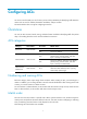
Configuring ACLs An access control list (ACL) is a set of rules (or permit or deny statements) for identifying traffic based on criteria such as source IP address, destination IP address, and port number. The Web interface does not support configuring IPv6 ACLs. Overview You can use ACLs in QoS, firewall, routing, and other feature modules for identifying traffic. The packet drop or forwarding decisions varies with the modules that use ACLs.
-
• config—Sorts ACL rules in ascending order of rule ID. A rule with a lower ID is matched before a rule with a higher ID. If you use this method, carefully check the rules and their order. • auto—Sorts ACL rules in depth-first order. Depth-first ordering makes sure any subset of a rule is always matched before the rule. Table 1 lists the sequence of tie breakers that depth-first ordering uses to sort rules for each type of ACL.
-
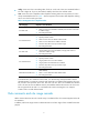
Rule numbering ACL rules can be manually numbered or automatically numbered. This section describes how automatic ACL rule numbering works. Rule numbering step If you do not assign an ID to the rule you are creating, the system automatically assigns it a rule ID. The rule numbering step sets the increment by which the system automatically numbers rules. For example, the default ACL rule numbering step is 5.
-
Configuration guidelines When you configure an ACL, follow these guidelines: • You cannot create a rule with, or modify a rule to have, the same permit/deny statement as an existing rule in the ACL. • You can only modify the existing rules of an ACL that uses the rule order of config. When you modify a rule of such an ACL, you may choose to change just some of the settings, in which case the other settings remain the same.
-
Complete the following tasks to configure an Ethernet frame header ACL: Task Remarks Required. 1. Create an Ethernet frame header ACL. 2. Configuring an Ethernet frame header ACL rule. For more information, see "Creating an ACL". Required. Creating an ACL 1. Select Firewall > ACL from the navigation tree. All existing IPv4 basic ACL, IPv4 advanced ACLs, and Ethernet frame header ACLs will be displayed in the right pane. Figure 1 ACL list 2. Click Add to enter the ACL configuration page.
-
Table 2 Configuration items Item Description ACL Number Enter a number for the ACL. Select a match order for the ACL. Available values are: Match Order • Config—Sorts ACL rules in ascending order of rule ID. • Auto—Sorts ACL rules in depth-first order. Description Enter a description for the ACL. Configuring an IPv4 basic ACL rule 1. Select Firewall > ACL from the navigation tree. 2. Click the icon for an IPv4 basic ACL to display all existing rules of the ACL.
-
Table 3 Configuration items Item Description Select the Rule ID box, and enter a number for the rule. Rule ID If you do not specify a rule number, the system automatically assigns one to the rule. If the rule already exists, the configuration overwrites the old rule. Select the operation to be performed for packets matching the rule: • Permit—Allows matching packets to pass. • Deny—Denies matching packets. Operation Select a time range for the rule. If you select None, the rule is always effective.
-
Figure 6 IPv4 Advanced ACL rule configuration page 4. Configure an IPv4 advanced ACL rule as described in Table 4. 5. Click Apply. Table 4 Configuration items Item Description Select the Rule ID box, and enter a number for the rule. Rule ID If you do not specify the rule number, the system assigns one automatically. If the rule already exists, the configuration overwrites the old rule.
-
Item Description Source IP Address Select the Source IP Address box, and enter a source IP address and source wildcard, in dotted decimal notation. Source Wildcard Destination IP Address Destination Wildcard Select the Destination IP Address box, and enter a destination IP address and destination wildcard, in dotted decimal notation. Specify the VPN. VPN Instance If you select None, the rule applies to only non-VPN packets. Select the protocol to be carried over by IP.
-
Figure 7 List of Ethernet frame header ACL rules 3. Click Add to enter the configuration page for Ethernet frame header ACL rules. Figure 8 Ethernet frame header ACL rule configuration page 4. Configure an Ethernet frame header ACL rule as described in Table 5. 5. Click Apply. Table 5 Configuration items Item Description Select the Rule ID box, and enter a number for the rule. Rule ID If you do not specify the rule number, the system assigns one automatically.
-
Item Description Destination MAC Address Select the Destination MAC Address box, and specify the destination MAC address and wildcard. Destination Wildcard LSAP Type Select the LSAP Type box, and specify the DSAP and SSAP fields in the LLC encapsulation by configuring the following two items: LSAP Wildcard • LSAP Type—Specifies the encapsulation format. • LSAP Wildcard—Specifies the LSAP mask.
-
Figure 9 Network diagram Configuring Firewall CAUTION: The three ACL rules must be configured in the shown order. 1. Create a periodic time range of Saturday and Sunday: a. Select Resource > Time Range from the navigation tree. b. Click Add. c. Enter time in the Name field. Select the Periodic Time Range box. Select the Sun. and Sat. boxes. d. Click Apply. Figure 10 Creating a time range 2. Create IPv4 basic ACL 2000. a. Select Firewall > ACL from the navigation tree. b. Click Add. c.
-
Figure 11 Creating an IPv4 basic ACL 3. Create a rule to allow Host A to access Firewall: a. Click the icon for ACL 2000. b. Click Add. c. Select Permit from the Operation list. Select the Source IP Address box and enter 192.168.1.2 and 0.0.0.0 in the following fields. d. Click Apply. Figure 12 Configuring a rule to allow Host A to access Firewall 4. Create a rule to deny access of other hosts to Firewall on Saturday and Sunday: a. On the page displaying the rules of ACL 2000, click Add. b.
-
Figure 13 Configuring an IPv4 basic ACL rule to deny access of other hosts to Firewall on Saturday and Sunday 5. Configure an IPv4 basic ACL rule to allow other hosts to access Firewall: a. On the page displaying rules of ACL 2000, click Add. b. Select Permit. c. Click Apply. Figure 14 Configuring an IPv4 basic ACL rule to allow other hosts to access Firewall 6. Associate HTTP service with IPv4 basic ACL 2000: a. Select Device Management > Service Management from the navigation tree. b.
-
Figure 15 Associating HTTP service with ACL 2000 Configuring the ACL at the CLI Configuration task list Task Remarks Configuring a basic ACL Required. Configuring an advanced ACL Configure at least one task. Configuring a basic ACL is applicable to IPv4 and IPv6. Configuring an Ethernet frame header ACL Configuring an Ethernet frame header ACL is applicable to IPv4. Optional. Copying an ACL Applicable to IPv4 and IPv6. Enabling ACL acceleration for an IPv4 basic or IPv4 advanced ACL Optional.
-
Step Command Remarks By default, no ACL exists. Create an IPv4 basic ACL and enter its view. acl number acl-number [ name acl-name ] [ match-order { auto | config } ] Configure a description for the IPv4 basic ACL. description text Set the rule numbering step. step step-value 5. Create or edit a rule. rule [ rule-id ] { deny | permit } [ counting | fragment | logging | source { source-address source-wildcard | any } | time-range time-range-name | vpn-instance vpn-instance-name ] * 6.
-
Step Command Remarks 5. Create or edit a rule. rule [ rule-id ] { deny | permit } [ counting | fragment | logging | routing [ type routing-type ] | source { source-address source-prefix | source-address/source-prefix | any } | time-range time-range-name | vpn-instance vpn-instance-name ] * 6. Add or edit a rule comment. rule rule-id comment text 7. Add or edit a rule range remark. By default, an IPv6 basic ACL does not contain any rule.
-
Step Command Remarks 5. Create or edit a rule.
-
Step Command Remarks rule [ rule-id ] { deny | permit } protocol [ { { ack ack-value | fin fin-value | psh psh-value | rst rst-value | syn syn-value | urg urg-value } * | established } | counting | destination { dest-address dest-prefix | dest-address/dest-prefix | any } | destination-port operator port1 [ port2 ] | dscp dscp | flow-label flow-label-value | fragment | icmp6-type { icmp6-type icmp6-code | icmp6-message } | logging | routing [ type routing-type ] | source { source-address source-prefix | s
-
Step Command Remarks By default, an Ethernet frame header ACL does not contain any rule. 5. Create or edit a rule. rule [ rule-id ] { deny | permit } [ cos vlan-pri | counting | dest-mac dest-address dest-mask | { lsap lsap-type lsap-type-mask | type protocol-type protocol-type-mask } | source-mac source-address source-mask | time-range time-range-name ] * 6. Add or edit a rule comment. rule rule-id comment text Add or edit a rule range remark. rule [ rule-id ] remark text 7. Optional.
-
Enabling ACL acceleration for an IPv4 basic or IPv4 advanced ACL CAUTION: • ACL acceleration is not available for ACLs that contain a non-contiguous wildcard mask. • After you modify an ACL with ACL acceleration enabled, disable and re-enable ACL acceleration to ensure correct rule matching. ACL acceleration speeds up ACL lookup. The acceleration effect increases with the number of ACL rules. ACL acceleration uses memory.
-
Task Command Remarks Clear statistics for one or all IPv4 basic, IPv4 advanced, and Ethernet frame header ACLs. reset acl counter { acl-number | all | name acl-name } Available in user view. Clear statistics for one or all IPv6 basic and advanced ACLs. reset acl ipv6 counter { acl6-number | all | name acl6-name } Available in user view. IPv4 ACL configuration example IPv4 ACLs are usually used together with NAT. For IPv4 configuration examples, see NAT and ALG Configuration Guide.
-
department to the database server during working hours, and one rule denies access from other departments to the database server.
-
[Firewall] display acl ipv6 3000 Advanced IPv6 ACL 3000, named -none-, 3 rules, ACL's step is 5 rule 0 permit ipv6 source 1001::/16 destination 1000::100/128 rule 5 permit ipv6 source 1002::/16 destination 1000::100/128 time-range work (4 times matched) (Active) rule 10 deny ipv6 destination 1000::100/128 (4 times matched) The output shows rule 5 is active. Rule 5 and rule 10 have been matched four times as the result of the ping operations.
-
Configuring security zones Overview In traditional firewall security policy applications, a firewall connects an internal network and an external network and firewall security policies are deployed on inbound and outbound interfaces. With the development of firewall technologies, a firewall is now connecting the DMZ as well as the internal network and external network, and tends to provide more interfaces (for example, over ten physical interfaces) to connect more network segments.
-
Figure 17 Network diagram When the source zone is not any, the destination zone cannot be any either. The source zone can be any, but configuring the source zone as any might cause the device unconfigurable. To avoid this problem, the system defines the rule that the Management zone does not belong to the any zone. Configuring the security zone in the Web interface Recommended configuration procedure Step Remarks Optional. 1.
-
Creating a security zone 1. Select Device Management > Zone from the navigation tree to enter the security zone management page. Figure 18 Security zone management page 2. Click Add. Figure 19 Creating a security zone 3. Configure the security zone as described in Table 6. 4. Click Apply. Table 6 Configuration items Item Zone ID Zone Name Description Specify the zone ID. The value range depends on the device model. For more information, see Table 7. Specify the zone name, which cannot be any.
-
Table 7 Value range for the Zone ID argument Hardware Value range F1000-A-EI/F1000-S-EI 1 to 512 F1000-E 1 to 1024 F5000 1 to 1024 F5000-S/F5000-C 1 to 1024 VPN firewall modules 1 to 1024 20-Gbps VPN firewall modules 1 to 1024 Adding members to the security zone 1. Select Device Management > Zone from the navigation tree to enter the security zone management page (see Figure 18). 2. Click the icon for the security zone. Figure 20 Modifying a security zone 3.
-
4. Click Apply. Table 8 Configuration items Item Description Zone ID Display the zone ID. Zone Name Display the zone name. Set the preference of the specified security zone. Preference By default, packets from a high priority security zone to a low priority security zone are allowed to pass. Share Set whether the specified security zone can be referenced by other VDs. Virtual Device Display the VD to which the security zone belongs. Set the interfaces to be added to the security zone.
-
Configuration considerations Three security zones are needed: one for the internal users, one for the servers, and one for the external users, in the order of priority (from high to low). The default zones Trust, DMZ, and Untrust can answer the requirements for security zones. To prepare the firewall for zone-based security policy deployment, configure the firewall as follows: • Add the port connected to the internal network (GigabitEthernet 0/3) to security zone Trust.
-
Figure 22 Configuring the Trust zone 2. Add interface GigabitEthernet 0/1 to security zone DMZ: a. Click the icon for security zone DMZ. b. Select interface GigabitEthernet0/1. c. Click Apply. d. Click Back to return to the security zone management page.
-
Figure 23 Configuring the DMZ zone 3. Add interface GigabitEthernet 0/2 to security zone Untrust: a. Click the icon for security zone Untrust. b. Select interface GigabitEthernet0/2. c. Click Apply. d. Click Back to return to the security zone management page.
-
Figure 24 Configuring the Untrust zone Configuring the security zone at the CLI Security zone configuration task list Task Remarks Creating a security zone Optional Setting the priority of a security zone Optional Enabling the share attribute of a security zone Optional Adding interfaces to a security zone Required Creating an interzone instance Optional Configuring a security zone To configure a security zone for a VD, create the VD first.
-
Creating a security zone When creating a security zone, you must specify a security zone name and a security zone ID that are respectively unique on the device. To enter the view of an existing security zone, you can specify the security zone name, or specify both the security zone name and security zone ID. If you specify both the security zone name and security zone ID, make sure the two arguments identify the same security zone.
-
To enable the share attribute of a security zone: Step Command Remarks 1. Enter system view. system-view N/A 2. Enter VD system view. switchto vd vd-name Required for a security zone of a non-default VD. 3. Enter security zone view. zone name zone-name [ id zone-id ] N/A 4. Enable the share attribute of the security zone. share enable By default, the share attribute of a security zone is disabled, and only the native VD can use the security zone.
-
The destination zone for an interzone instance must belong to the same VD as the source zone, or have its share attribute enabled. To specify a security zone that belongs to a different VD than the source zone as the destination zone, enter the zone name in the format vd-name-zone-id. For example, to specify VD test's zone 2 as the destination zone, enter test-2. To create an interzone instance: Step Command Remarks 1. Enter system view. system-view N/A 2. Enter VD system view.
-
• Deploy the servers in security zone DMZ, and add the interface connected to the servers (GigabitEthernet 0/1) to security zone DMZ. • Create interzone instances and enable ASPF for the instances. Configuration procedure # Add interface GigabitEthernet 0/0 to security zone Trust. system-view [Firewall] zone name Trust [Firewall-zone-Trust] import interface gigabitethernet 0/0 [Firewall-zone-Trust] quit # Add interface GigabitEthernet 0/1 to security zone DMZ.
-
Managing services This chapter describes how to manage the following services in the Web interface: • FTP service—Transfers files between server and client over a TCP/IP network. • Telnet service—Provides remote login and virtual terminal functions. • SSH service—Offers an approach to securely logging in to a remote device. By encryption and strong authentication, it protects devices against attacks such as IP spoofing and plain text password interception.
-
Table 9 Configuration items Item Description Enable FTP service. FTP ACL. Enable or disable the FTP service. The FTP service is disabled by default. Associate the FTP service with an ACL. Only the clients that pass the ACL filtering are permitted to use the FTP service. You can view this configuration item by clicking the expanding button in front of FTP. Telnet Enable Telnet service. Enable or disable the Telnet service. SSH Enable SSH service. Enable or disable the SSH service.
-
Item Description Associate the HTTPS service with an ACL. Only the clients that pass the ACL filtering are permitted to use the HTTPS service. ACL. You can view this configuration item by clicking the expanding button in front of HTTPS. Service management configuration examples HTTP configuration example Network requirements As shown in Figure 27, Host A can always access the firewall through HTTP, but other hosts can access the firewall through HTTP only on working days.
-
Figure 28 Creating a time range Creating a basic ACL 1. Select Firewall > ACL from the navigation tree. 2. Click Add. The page for adding ACL appears. 3. Create ACL 2000 as shown in Figure 29. 4. Select the match order Config. 5. Click Apply. Figure 29 Creating an ACL Creating an ACL rule to allow Host A to access Firewall all the time 1. Click the 2000. 2. Click Add.
-
b. Select the Source IP Address box. c. Enter 192.168.1.2 in the Source IP Address field. d. Enter 0.0.0.0 in the Source Wildcard field. 4. Click Apply. Figure 30 Configuring a rule to allow Host A to access Firewall all the time Creating a rule to disable other hosts from accessing Firewall on Saturday and Sunday 1. Click Add on the page which displays the rules of ACL 2000. 2. Create an ACL rule as shown in Figure 31. a. Select Deny as the operation. b. Select time as the time range. c.
-
Figure 32 Configuring an ACL rule to allow other hosts to access Firewall NOTE: The three ACL rules must be configured in the shown order. Associating HTTP service with ACL 2000 1. Select Device Management > Service Management from the navigation tree. 2. Associate HTTP service with ACL 2000 as shown in Figure 33. a. Click the expansion triangle sign before HTTP to expand the configuration area. b. Enter 2000 in the ACL field. 3. Click Apply.
-
To meet the requirements, configure the firewall as an HTTPS server and apply for a certificate for the firewall. The name of the certificate authority (CA) that issues certificates to the firewall and the host is CA server. This example uses a Windows server as the CA that has the Simple Certificate Enrollment Protocol (SCEP) component installed. Before proceeding with the following configuration, make sure that the firewall, the host, and CA can reach each other.
-
Figure 35 Adding a PKI entity Creating a PKI domain 1. Select VPN > Certificate Management > Domain from the navigation tree. 2. Click Add. The page for adding a PKI domain appears. 3. Add PKI domain as shown in Figure 36. a. Enter 1 as the PKI domain name. b. Enter CA server as the CA identifier. c. Select en as the local entity. d. Select RA as the authority for certificate request. e. Enter http://10.1.2.2/certsrv/mscep/mscep.dll as the URL for certificate request. 4. Click Apply. 5.
-
Figure 36 Adding a PKI domain Generating an RSA key pair 1. Select VPN > Certificate Management > Certificate from the navigation tree. 2. Click Create Key. The page for generating RSA key pair appears. 3. Enter 1024 in the Key Length field. 4. Click Apply. Figure 37 Generating an RSA key pair Retrieving the CA certificate 1. Select VPN > Certificate Management > Certificate from the navigation tree. 2. Click Retrieve Cert. The page for retrieving a certificate appears. 3.
-
Figure 38 Retrieving a certificate Requesting a local certificate 1. Select VPN > Certificate Management > Certificate from the navigation tree. 2. Click Request Cert. The page for requesting a certificate appears. 3. Select 1 as the PKI domain name. 4. Click Apply. Figure 39 Requesting a certificate 5. Click OK when the system displays "Certificate request has been submitted".
-
Figure 40 Enabling HTTPS service 2. Select the Enable HTTPS service box. 3. Select CN=http-server1 from the certificate list. 4. Click Apply. Verifying the configuration Open an Internet browser on the host and type https://10.1.1.1 in the address bar to enter the Web login interface. Enter the username, password, and verification code, and then click Log in. You can access the firewall.
-
Configuring address resources Address resource overview In the Web interface, address resources are classified into the following categories: IP address resource, IP address group resource, MAC address resource, and MAC address group resource. They can be referenced by interzone policies to define packet match criteria. Matching packets are permitted or denied based on the interzone policy configuration. For more information, see "Configuring an interzone policy.
-
Figure 42 Host address resource configuration page 3. Configure the host address resource as described in Table 10. 4. Click Apply. Table 10 Configuration items Item IP Address Host name Description Select either of them as the address resource type. Specify the name for the host address resource. Name IMPORTANT: All resources (excluding the time range resources) must have unique names. Description Describe the host address resource in brief.
-
The address range resource list page appears. Figure 43 Address range resource list 3. Click Add. The page for configuring address range resource appears. Figure 44 Address range resource configuration page 4. Configure the address range resource as described in Table 11. 5. Click Apply. Table 11 Configuration items Item Description Specify the name for the address range resource. Name IMPORTANT: All resources (excluding the time range resources) must have unique names.
-
Item Description Address Range Specify a start IP address and an end IP address to define an address range. The end address cannot be smaller than the start IP address. Specify the IP addresses to be excluded: Exclude IP Address • Enter an IP address in the field next to the Add button, and then click Add to add it to the excluded IP address list. • Select one or more IP addresses in the excluded IP address list, and then click Remove to remove them from the list.
-
Figure 46 Subnet address resource configuration page 4. Configure the subnet address resource as described in Table 12. 5. Click Apply. Table 12 Configuration items Item Description Specify the name for the subnet address resource. Name IMPORTANT: All resources (excluding the time range resources) must have unique names. Description Describe the subnet address resource in brief. IP/Wildcard Specify an IP address and a wildcard to define an address range.
-
Figure 47 IP address group resource list 2. Click Add. The page for configuring IP address group resource appears. Figure 48 IP address group resource configuration page 3. Configure the IP address group resource as described in Table 13. 4. Click Apply. Table 13 Configuration items Item Description Specify the name for the address group resource. Name IMPORTANT: All resources (excluding the time range resources) must have unique names. Description Describe the address group resource in brief.
-
Item Description Add or remove IP address resources: • Select one or more IP address resources from the Available Group Members list and then click the << button to add them to the Group Members list. Group Members • Select one or more IP address resources from the Group Members list and then click the >> button to remove them from the Group Members list. The Available Group Members list contains all the host resources, address range resources, and subnet address resources that have been configured.
-
Table 14 Configuration items Item Description Specify the name for the MAC address resource. Name IMPORTANT: All resources (excluding the time range resources) must have unique names. Description Describe the MAC address resource in brief. Add or remove MAC address resources: • Enter a MAC address in the field next to the Add button, and then click Add to add MAC Address it to the MAC List. • Select one or more MAC addresses in the MAC list, and then click Remove to remove them from the list.
-
Figure 52 MAC address group configuration page 4. Configure the MAC address group as described in Table 15. 5. Click Apply. Table 15 Configuration items Item Description Specify the name for the MAC address group resource. Name IMPORTANT: All resources (excluding the time range resources) must have unique names. Description Describe the MAC address group resource in brief.
-
For more information, see "Configuring service resources." Exporting configuration 1. Click Export on any resource list page. The Export dialog box appears. Figure 53 Export configurations 2. Choose the types of configurations you want to export by selecting the boxes. 3. Click Apply. 4. On the dialog box that appears, click Save. 5. Set the path and name of the file for saving the configurations on the local host. 6. Click Save to export and save the selected configurations to the file.
-
• MAC address object—A MAC address object comprises one or more MAC addresses. • MAC address group object—A MAC address group object comprises MAC address objects, MAC address group objects, or both. At the CLI, address objects also include service objects and service group objects. For more information, see "Configuring service resources." IP address objects support only IPv4 addresses. One group object can comprise other group objects, and a member group object can also comprise other group objects.
-
Step 5. Add a host IP address or host name to the object. Command Remarks • Add a host IP address to the object: Use either command to add one type to the object. • Add a host name to the object: By default, a host address object has no members. host address ip-address host name host-name Configuring an address range object An address range object can comprise only one range of IP addresses. If you execute the range command multiple times, the most recent configuration takes effect.
-
Step Command Remarks By default, no subnet address object is configured. Create a subnet address object and enter subnet address object view. object network subnet name 4. Configure a description for the object. description description-string By default, no description is configured for an object. 5. Add a subnet IP address to the object. subnet { net-address wildcard-mask | exclude ip-address } By default, a subnet address object has no members. 3.
-
Step 4. 5. Command Configure a description for the object. Add a MAC address to the object. Remarks description description-string Optional. By default, no description is configured for an object. By default, a MAC address object has no members. mac-address mac-address A MAC address object can comprise multiple MAC addresses. To add multiple MAC addresses, execute this command multiple times. Configuring a MAC address group object Step Command Remarks 1. Enter system view. system-view N/A 2.
-
Task Command Remarks Display a specific group object. display object-group name object-group-name [ vd vd-name ] Available in any view.
-
Configuring service resources Overview A service resource defines a service by specifying the protocol to be carried by IP and the protocol-specific items. It might be referenced by interzone policy as a packet match criterion. An interzone policy determines whether to allow a packet to pass through. For more information about interzone policies, see Security Configuration Guide. Service resources include three categories: • Default service resources—Created by the device during initialization.
-
Configuring a customized service resource 1. From the navigation tree, select Resource > Service > Customized Service. All existing customized service resources are displayed, as shown in Figure 56. Figure 56 Customized service resource list 2. Click Add. The customized service resource configuration page appears. Figure 57 Customized service resource configuration page 3. Configure the parameters, as described in Table 16. 4. Click Apply.
-
Item TCP UDP ICMP Other Protocol Description Source Port Set the source and destination TCP port ranges in the fields. These fields are available after you select TCP. Destination Port • To define a single port, type the same port numbers in the two fields in a row. • To define a port range, type two different port numbers. Make sure the second Source Port Set the source and destination UDP port ranges in the fields. These fields are available after you select UDP.
-
Configuring a service group resource 1. From the navigation tree, select Resource > Service > Service Group. All existing service group resources are displayed, as shown in Figure 58. Figure 58 Service group resource list 2. Click Add. The service group resource configuration page appears. Figure 59 Service group resource configuration page 3. Configure the parameters, as described in Table 18. 4. Click Apply.
-
Item Description Add or remove service resources: • Select one or more service resources from the Available Group Members list and then click << to add them to the Group Members list. Group Members • Select one or more service resource from the Group Members list and then click >> to remove them from the Group Members list. The Available Group Members list contains all default and customized service resources that have been configured.
-
Figure 61 Importing the configurations Configuring the service resource at the CLI Service resource is also referred to as service objects at the CLI: • Service object—A service object comprises a single protocol. • Service group object—A service group object comprises service objects, service group objects, or both. In addition to service object and service group object, there are also IP object, IP address group object, MAC address object, and MAC address group object at the CLI.
-
Step 5. Add a protocol to the object. Command Remarks service { protocol | icmp icmp-type icmp-code | { tcp | udp } [ source-port source-port-start [ source-port-end ] ] [ destination-port destination-port-start [ destination-port-end ] ] } By default, a user-defined service object comprises no protocol. A service object can comprise only one protocol. If you execute this command multiple times, the most recent configuration takes effect.
-
Configuring a time range resource Overview A time range resource defines a time range, which can be referenced by an ACL or an interzone policy to control when a rule is effective. The following basic types of time range are available: • Periodic time range—Recurs periodically on a day or days of the week. • Absolute time range—Represents only a period of time and does not recur.
-
Figure 63 Time range resource configuration page 3. Configure the time range resource as described in Table 19. 4. Click Apply. Table 19 Configuration items Item Description Name Enter the name for the time range resource. If a time range resource with the specified name already exists, you can add time ranges to the time range resource. Otherwise, you can add a new time range resource. Periodic Time Range Start Time.
-
Step Command Remarks By default, no time range exists. 2. Configure a time range. time-range time-range-name { start-time to end-time days [ from time1 date1 ] [ to time2 date2 ] | from time1 date1 [ to time2 date2 ] | to time2 date2 } 3. Display the configuration and status of one or all time ranges.
-
Configuring an interzone policy Overview An interzone policy is a set of policy rules or IPv4 advanced ACLs to implement security control over packets between a source and a destination security zone. These two zones define an interzone instance. The interzone policy matches the first packet of a traffic flow against the rules or ACLs. If a match is found, the device stops the match process and takes the action defined in the rule over the packet and all subsequent packets of the flow.
-
At the CLI, ACLs are matched in the order that they are displayed in the output of the display this command in interzone instance view. • For information about ACLs, see "Configuring ACLs." Configuring the interzone policy rules in the Web interface Configuring an interzone policy rule Before configuring an interzone policy rule, complete the following tasks: • Create security zones to which you will apply an interzone policy (see "Configuring security zones").
-
Figure 64 Interzone policy rule list Table 20 Operations you can perform on the list Field Source Address/Destination Address/Source MAC/Destination MAC Service Operation Click an address (except any_address and any_mac) to enter the address resource configuration page, where you can view and modify the address resource configuration. For information about address resources, see "Configuring address resources.
-
NOTE: The "Match Counter" field refers to the number of times that the interzone policy rule has been matched. Click Clear match counter to clear the match counters of all interzone policy rules and interzone policy groups. 2. Click Add to enter the interzone policy rule (that is the ACL rule) configuration page. Figure 65 Interzone policy rule configuration page 3. Configure an interzone policy rule as described in Table 21. 4. Click Apply.
-
Item Description Configure a source address resource for the rule by creating an address resource or referencing an existing address resource. • If you select the New IP Address option, specify an IP address and wildcard. After Source IP Address you apply the configuration, the system automatically creates a subnet address resource. For example, if you enter 1.1.1.1/0.0.0.255, a subnet address resource is created with the resource name being 1.1.1.1/0.0.0.255.
-
Item Description Set the source and destination MAC addresses. Source MAC Address • Enter a new MAC address in the field. The new MAC address will be a MAC address resource after you apply your configuration and the MAC address name is the MAC address. • You can also select from the MAC address (group) resource list or click Multiple to select more MAC addresses (groups). Available MAC address (group) resources are configured on the page you enter by selecting Resource > Address.
-
Replicating an interzone policy rule 1. Select Firewall > Security Policy > Interzone Policy from the navigation tree to enter the interzone policy rule list page, as shown in Figure 64. 2. Click the icon for a rule to enter the page for creating an interzone policy rule based on the existing one. The new rule takes the settings of the existing one as its default settings. You can make changes as desired. 3. Configure the rule as described in Table 21. 4. Click Apply.
-
2. Enter the IP address in the field, and choose whether you want to query by source or destination IP address from the list. 3. Click Search. The page displays the policies with the source or destination IP address. Configuring an interzone policy group Configuration prerequisites Before configuring an interzone policy group, complete the following tasks: • Create security zones to which you will apply an interzone policy (see "Configuring security zones").
-
Figure 69 Interzone policy group configuration page 3. Configure the interzone policy group as described in Table 23. 4. Click Apply. Table 23 Configuration items Item Source Zone Description Select a source zone for the interzone policy group. Any means all zones on the virtual device. Select a destination zone for the interzone policy group. Dest Zone Any means all zones on the virtual device. Virtual device name-Any means all shared zones on the virtual device with the specified name.
-
Exporting and importing configurations In the Web interface, you can import and export the configuration of interzone policies (including interzone policy rules and interzone policy groups), address resources, and service resources (excluding predefined service resources) through a file, facilitating the interzone policy configuration. For more information about service resources, see "Configuring service resources." For more information about address resources, see "Configuring address resources.
-
3. Click Browse, and then choose the configuration file. 4. Only the files suffixed with .xml can be imported. 5. Click Apply to import all configurations in the file. Displaying packet statistics of an interzone policy 1. Select Firewall > Security Policy > Policy Matching Statistics from the navigation tree. 2. Select the source and target zone, and then click Search. The page displays the results matching the search conditions. Table 24 describes the fields on the page.
-
Figure 73 Network diagram (Method 1) Configuring an interzone policy rule on the firewall 1. Create a periodic time range from 8:00 to 18:00 on working days (from Monday through Friday): a. Select Resource > Time Range from the navigation tree. b. Click Add. c. Enter worktime in the Name field. Select the Periodic Time Range box. Set the start time to 8:00. Set the end time to 18:00. Select the Mon., Tues., Wed., Thurs., and Fri., boxes. d. Click Apply. Figure 74 Configuring a time range 2.
-
Figure 75 Configuring an IP address resource 3. Configure an access rule for host public to access the external network at any time: a. Select Firewall > Security Policy > Interzone Policy from the navigation tree. b. Click Add. c. Select Trust as the source zone and Untrust as the destination zone. d. Select public as the address. e. Select Permit as the filter action. f. Select the Enable the rule box. Select the Continue to add next rule box. g. Click Apply.
-
Figure 76 Allowing the host public to access the external network at any time 4. Configure an access rule to deny the access of all the other hosts to the external network during working time: After the last configuration step, you will enter the interzone policy rule configuration page, with the source and destination zone selected for the last rule. a. Select Deny as the filter action. b. Select worktime as the time range. c. Select the Status box. d. Click Apply.
-
Figure 77 Denying all the other hosts' access to the external network during working time (Method 2) Configuring an interzone policy group on the firewall 1. Create a periodic time range from 8:00 to 18:00 on working days (from Monday through Friday): a. Select Resource > Time Range from the navigation tree. b. Click Add. c. Enter worktime in the Name field. Select the Periodic Time Range box. Set the start time to 8:00. Set the end time to 18:00. Select the Mon., Tues., Wed., Thurs., and Fri., boxes. d.
-
Figure 79 Configuring ACL 3000 3. Configure a rule for ACL 3000, allowing host public to access the external network at any time: a. Click the icon for ACL 3000 to enter the page that lists the ACL rules. b. Click Add. c. Select Permit as the operation. Select the Source IP Address box, and enter 10.1.1.12 and 0.0.0.0 in the following fields. d. Click Apply. Figure 80 Allowing the host Public to access the external network at any time 4.
-
Figure 81 Denying all the other hosts' access to the external network during working time 5. Configure the interzone policy group: a. Select Firewall > Security Policy > Interzone Policy Group from the navigation tree to enter the interzone policy group list page. b. Click Add to enter the interzone policy group configuration page. c. Select Trust as the source zone. Select Untrust as the destination zone. d. Select 3000 under Available ACLs, and click << to add it to the selected ACL list. e.
-
Figure 82 Configuring the interzone policy group Configuring the interzone policy rules at the CLI Interzone policy rule configuration task list Task Remarks Creating an interzone policy rule Required. Referencing objects in an interzone policy rule Required. Enabling an interzone policy rule Required. Enabling interzone policy acceleration Optional. Moving an interzone policy rule Optional.
-
Creating an interzone policy rule Step Command Remarks 1. Enter system view. system-view N/A 2. Enter VD system view. switchto vd vd-name Required for a VD. 3. Create an interzone instance and enter interzone instance view. interzone source source-zone-name destination destination-zone-name By default, no interzone instance exists. Create an interzone policy rule and its view. 4. By default, no interzone policy rule exists in an interzone instance.
-
Step 4. 5. 6. 7. Enter interzone policy rule view. Reference a source IP object in the interzone policy rule. Reference a destination IP object in the interzone policy rule. Reference a service object in the interzone policy rule. Command Remarks rule [ rule-id ] { deny | permit } [ content-filter policy-template-name | logging | time-range time-range-name ] * N/A By default, no source IP object is referenced in an interzone policy rule.
-
Enabling an interzone policy rule Step Command Remarks 1. Enter system view. system-view N/A 2. Enter VD system view. switchto vd vd-name Required for a VD. 3. Enter interzone instance view. interzone source source-zone-name destination destination-zone-name N/A 4. Enter interzone policy rule view. rule [ rule-id ] { deny | permit } [ content-filter policy-template-name | logging | time-range time-range-name ] * N/A 5. Enable the interzone policy rule.
-
Configuring the interzone policy group Interzone policy group configuration task list Task Remarks Creating the interzone policy group Required. Enabling the interzone policy group Required. Moving an ACL in the interzone policy group Optional. Configuration prerequisites Before configuring the interzone policy group, complete the following tasks: • Create a VD (see System Management and Maintenance Configuration Guide). • Configure IPv4 ACLs (see "Configuring ACLs").
-
Step Command Remarks 2. Enter VD system view. switchto vd vd-name Required for a VD. 3. Enter interzone instance view. interzone source source-zone-name destination destination-zone-name N/A 4. Move an ACL in the interzone policy. move rule acl acl-number before insert-acl-number Optional. Displaying and maintaining interzone policies Task Command Remarks Display interzone policy configuration.
-
Figure 83 Network diagram Configuration procedure 1. Create a time range named work to cover 8:00 to 18:00 on working days. system-view [Firewall] time-range work 8:0 to 18:0 working-day 2. Configure security zones: # Create a security zone named president, and add interface GigabitEthernet 0/2 to the security zone.
-
[Firewall-object-network-president] quit # Create a subnet address object named finance, and add subnet IP address 192.168.2.0/24 to the object. [Firewall] object network subnet finance [Firewall-object-network-finance] subnet 192.168.2.0 0.0.0.255 [Firewall-object-network-finance] quit # Create a subnet address object named market, and add subnet IP address 192.168.3.0/24 to the object. [Firewall] object network subnet market [Firewall-object-network-market] subnet 192.168.3.0 0.0.0.
-
[Firewall-interzone-finance-database-rule-1] rule enable [Firewall-interzone-finance-database-rule-1] quit [Firewall-interzone-finance-database] quit # Create an interzone instance from source zone market to destination zone database, configure a rule to deny access from the marketing department to the financial database server through HTTP at any time, and enable the rule.
-
2. Create IPv4 advanced ACL 3000, and configure three rules in the ACL. One rule permits access from the president office to the financial database server, one rule permits access from the financial department to the database server during working hours, and one rule denies access from any other department to the database server at any time. [Firewall] acl number 3000 [Firewall-acl-adv-3000] rule permit ip source 192.168.1.0 0.0.0.255 destination 192.168.0.
-
# Ping the financial database server from a PC of the marketing department during working hours. C:\> ping 192.168.0.100 Pinging 192.168.0.100 with 32 bytes of data: Request timed out. Request timed out. Request timed out. Request timed out. Ping statistics for 192.168.0.100: Packets: Sent = 4, Received = 0, Lost = 4 (100% loss), The output shows that the financial database server cannot be pinged.
-
Configuration procedure 1. Log in to the Web interface, and then select Wizard from the navigation tree to enter the main page of the configuration wizard. 2. Click the Firewall Policy Configuration hyperlink to enter the first page of the firewall policy configuration wizard. Figure 85 Firewall policy configuration wizard: 1/7 3. Configure the items on the page as described in Table 26. Table 26 Configuration items 4. Item Description Source Zone Specify the source zone of the firewall policy.
-
Figure 86 Firewall policy configuration wizard: 2/7 5. Configure the items on the page as described in Table 27. Table 27 Configuration items Item Description Specify the action to be taken for packets matching the firewall policy: Filter Action Content Filtering Policy Template • Permit—Allows matched packets to pass. • Deny—Drops matched packets. Specify the content filtering template to be applied to the packets that match the firewall policy.
-
6. Click Next to enter the third page of the firewall policy configuration wizard. Figure 87 Firewall policy configuration wizard: 3/7 7. Configure the items on the page as described in Table 28. Table 28 Configuration items Item Description Source IP Address (Group) Specify the source address or source address group resource for the firewall policy. Destination IP Address (Group) Specify the destination address or destination address group resource for the firewall policy.
-
8. Click Next to enter the fourth page of the firewall policy configuration wizard. Figure 88 Firewall policy configuration wizard: 4/7 9. Configure the item on the page as described in Table 29. Table 29 Configuration item Item Description Service (Group) Specify the service resource for the firewall policy.
-
10. Click Next to enter the fifth page of the firewall policy configuration wizard. Figure 89 Firewall policy configuration wizard: 5/7 11. Configure the item on the page as described in Table 30. Table 30 Configuration item Item Description Time Range Specify the time range resource for the firewall policy.
-
12. Click Next to enter the sixth page of the firewall policy configuration wizard. Figure 90 Firewall policy configuration wizard: 6/7 13. Configure the item on the page as described in Table 31. Table 31 Configuration item Item Description Enable Syslog Function Specify whether to keep a log of matched packets.
-
14. Click Next to enter the seventh page of the firewall policy configuration wizard. Figure 91 Firewall policy configuration wizard: 7/7 15. Select whether to save the current configuration to the configuration files to be used at next startup (including a cfg file and xml file), check that the settings are what you want, and then select the destination page: { { { Interzone policy page—Jumps to the page you can enter by selecting Firewall > Security Policy > Interzone Policy from the navigation tree.
-
Managing sessions Overview Session management is a common feature designed to implement session-based services such as NAT, ASPF, and intrusion protection. Session management regards packet exchanges at transport layer as sessions and updates the session status, or ages sessions out according to information in the initiator or responder packet. Session management allows multiple features to process the same service packet.
-
• Supports ICMP error packet mapping and allows the system to search for original sessions according to the payload of these packets. Because error packets are generated due to host errors, the mapping can help speed up the aging of the original sessions. • Supports persistent sessions, which are kept alive for a long period of time. Only TCP sessions in ESTABLISHED state can be specified as persistent sessions.
-
Figure 92 Session configuration 2. Configure the parameters as described in Table 32. 3. Click Apply.
-
Table 32 Configuration items Item Description Enable or disable unidirectional traffic detection. • When unidirectional traffic detection is enabled, the session management feature processes both the unidirectional and bidirectional traffic. • When unidirectional traffic detection is disabled, the session management feature processes only the bidirectional traffic.
-
Item Description FTP Session Aging Time Specify the FTP session aging time. MSN Session Aging Time Specify the MSN session aging time. QQ Session Aging Time Specify the QQ session aging time. SIP Session Aging Time Specify the SIP session aging time. Displaying session table information 1. Select Firewall > Session Table > Session Summary from the navigation tree. The session table appears. Figure 93 Session table Table 33 Field description 2.
-
Figure 94 Detailed information of a session Table 34 Field description Field Description Protocol Transport layer protocol, including TCP, UDP, ICMP, or RAWIP. Session status: State • • • • • • • • • • Accelerate. SYN. TCP-EST. FIN. UDP-OPEN. UDP-READY. ICMP-OPEN. ICMP-CLOSED. RAWIP-OPEN. RAWIP-READY. TTL Remaining lifetime of the session. Initiator: VD / ZONE / VPN / IP / PORT Initiator's virtual device/security zone/VPN instance/IP address/port number.
-
Figure 95 Global session statistics Table 35 Field description Field Description Current Session(s) Total number of sessions. Current TCP Session(s) Total number of current TCP half-open connections, TCP half-close connections, and full TCP connections in the system. Current TCP Half-Open Session(s) Number of current TCP half-open connections in the system. Current TCP Half-Close Session(s) Number of current TCP half-close connections in the system.
-
Field Description Received TCP Byte(s) Number of TCP bytes received. Received UDP Packet(s) Number of UDP packets received. Received UDP Byte(s) Number of UDP bytes received. Received ICMP Packet(s) Number of ICMP packets received. Received ICMP Byte(s) Number of ICMP bytes received. Received RAWIP Packet(s) Number of RAWIP packets received. Received RAWIP Byte(s) Number of RAWIP bytes received.
-
Figure 97 Session statistics configuration page 3. Enable the proper session statistics as described in Table 36. 4. Click Apply. Table 36 Configuration items Item Description Zone Select a security zone. Enable source zone statistics Enable collection of statistics on sessions with the source security zone being the specified security zone. Enable destination zone statistics Enable collection of statistics on sessions with the destination security zone being the specified security zone.
-
Figure 98 Session statistics by the IP address Table 37 Field description Field Description Total Connection Count Total number of current connections. Total Connection Rate Sampled connection establishment rate in a 5-second interval. TCP Connection Count Total number of TCP half-open connections, TCP half-close connections, and full TCP connections. TCP Half-Open Connection Count Number of TCP half-open connections. TCP Half-Close Connection Count Number of TCP half-close connections.
-
Field Description ICMP Packet Count Number of ICMP packets. ICMP Byte Count Number of ICMP bytes. RAWIP Packet Count Number of RAWIP packets. RAWIP Byte Count Number of RAWIP bytes. Displaying session statistics by the security zone 1. Select Firewall > Session Table > Statistics from the navigation tree. 2. Click the Zone Statistics tab. 3. Select the desired security zone and direction. 4. Click Search. The matching session statistics are displayed.
-
Field Description RAWIP Connection Count Number of current RAWIP connections. RAWIP Connection Rate Sampled RAWIP connection establishment rate in a 5-second interval. NOTE: A session cannot detect the changes of the security zone where the interface resides, security zone priority, and virtual device attributes. Regardless of these changes, an established session always forward packets until the session ages out.
-
Setting session aging time for application layer protocols For sessions in the READY (with UDP) or ESTABLISH (with TCP) state, you can set the session aging times according to the types of the application layer protocols to which the sessions belong. IMPORTANT: For a large amount of sessions (more than 800000), do not specify too short aging time. Otherwise, the console might be slow in response. To set session aging times based on application layer protocol type: Step Command Remarks 1.
-
Configuring the operating mode for session management By default, session management operates in bidirectional mode, and it can process only bidirectional sessions. You can set the operating mode to hybrid mode for processing both bidirectional sessions and unidirectional sessions. In a unidirectional session, packets in a specific direction can pass the device. In the hybrid mode, some features cannot function correctly, and system security is adversely affected.
-
Configuring session logging Session logs help track information about user access, IP address translation, and traffic, and can be sent to the log server or exported to the information center in flow log format. It can help network administrators in security auditing. Enabling session logging Step Command Remarks 1. Enter system view. system-view N/A 2. Enter system view of the virtual device. switchto vd vd-name Required for non-default virtual devices. 3.
-
Step Command Remarks 1. Enter system view. system-view N/A 2. Specify the flow log version. userlog flow export version version-number Optional. 3. Specify the source IP address for UDP packets carrying flow logs. userlog flow export source-ip ip-address 4. Specify the IP address and UDP port number of the flow log server. userlog flow export [ vpn-instance vpn-instance-name ] host ip-address udp-port 5. Specify to export flow logs to the information center. 1.0 by default. Optional.
-
Task Command Remarks Clear sessions. reset session [ vd vd-name ] [ source-ip source-ip ] [ destination-ip destination-ip ] [ protocol-type { icmp | raw-ip | tcp | udp } ] [ source-port source-port ] [ destination-port destination-port ] [ vpn-instance vpn-instance-name ] Available in user view. Clear session statistics. reset session statistics [ vd vd-name ] Available in user view. Clear flow logs in the buffer. reset userlog flow logbuffer Available in user view.
-
Configuring virtual fragment reassembly Overview To prevent service modules (such as IPSec, NAT and firewall) from processing packet fragments that arrive out of order, you can enable the virtual fragment reassembly feature. This feature can virtually reassemble the fragments of a datagram through fragment checking, sequencing and caching so as to make sure fragments arrive at service modules in order.
-
Figure 100 Virtual fragment reassembly configuration page 2. Configure the parameters as described in Table 39. 3. Click Apply. Table 39 Configuration items Item Description Specify a security zone to be configured with virtual fragment reassembly. Security Zone Enable Virtual Fragment Reassembly Specify max number of concurrent reassemblies The virtual fragment reassembly feature is effective in only the inbound direction of a security zone.
-
Virtual fragment reassembly configuration example Network requirements As shown in Figure 101, the host accesses the router through the firewall and NAT is enabled on interface GigabitEthernet 0/1 of the firewall. Enable virtual fragment reassembly for security zone Trust on the firewall to ensure secure and efficient NAT. Figure 101 Network diagram Configuring the host Configure a static route to the router. (Details not shown.) Configuring the firewall 1.
-
Figure 103 Enabling static NAT on an interface 4. Configure virtual fragment reassembly: a. Select Firewall > Session Table > Advanced from the navigation tree. b. Select Trust for Security Zone. c. Select the Enable Virtual Fragment Reassembly box. d. Click Apply. Figure 104 Configuring virtual fragment reassembly After the configuration, if the firewall receives disordered fragments from security zone Trust, it examines and reassembles them.
-
Step Command Remarks Create a security zone and enter security zone view. zone name zone-name [ id zone-id ] N/A 4. Enter interface view. interface interface-type interface-number N/A 5. Enable IP virtual fragment reassembly. ip virtual-reassembly [ drop-fragments | max-fragments number | max-reassemblies number | timeout seconds ] * By default, the feature is enabled. 6. Display fragment information in the security zone.
-
With the IP virtual fragment reassembly feature, the firewall checks, sequences, and caches fragments that do not arrive in order at GigabitEthernet0/2. You can use the display ip virtual-reassembly command to view related information.
-
Configuring ASPF Overview Application specific packet filter (ASPF) applications are based on zone management and session management. Zone management is an independent common module. It does not concern service packet processing; it only maintains information relevant to zones and provides policy interfaces for other modules.
-
Figure 107 Adding an ASPF policy 4. Configure the parameters as described in Table 40. 5. Click Apply. Table 40 Configuration items Item Source Zone Dest Zone Discard ICMP error packets Discard non-SYN initial TCP packets Description Select a source/destination zone to which the ASPF policy will be applied.. Set whether to discard ICMP error packets. If this box is not selected, ICMP error packets are allowed to pass. Set whether to discard initial TCP packets that are not SYN packets.
-
Configuration procedure 1. Configure zone 1 and zone 2, and specify security zones for the interfaces. (Details not shown) 2. Configure an ASPF policy: a. Select Firewall > Session Table > Advanced from the navigation tree. b. Click the ASPF tab. c. Click Add. d. Select zone 1 from the Source Zone list. e. Select zone 2 from the Dest Zone list. f. Click the Discard ICMP error packets box. g. Click Apply.
-
Configuring session acceleration Session acceleration can be configured only in the Web interface. Feature and hardware compatibility Hardware Session acceleration compatibility F1000-A-EI/F1000-S-EI Yes F1000-E Yes F5000 Yes F5000-S/F5000-C No VPN firewall modules Yes 20-Gbps VPN firewall modules No Overview In some specific applications, session acceleration helps improve system performance for setting up sessions.
-
• When session acceleration and active/standby failover are configured at the same time, session acceleration does not take effect, but will degrade the system performance. • If session acceleration is enabled, the system cannot perform abnormity detection for non-SYN initial TCP packets. • If session acceleration is enabled, the statistics of half-open and half-close sessions are not correct, and SYN Flood attack detection cannot be performed according to half-open and half-close session threshold.
-
Configuring connection limits Overview If a client in an internal network initiates a large number of connections to the external network through the device, the system resources of the device might be used up, and other users cannot access the network resources correctly. In addition, if an internal server receives a large number of connection requests from a client in a short time, the server might not be able to process them in time and cannot handle the connection requests from other clients.
-
Figure 112 Connection limit policies 3. Click Add to add a policy. 4. Configure the necessary parameters, and click 5. Repeat steps 3 and 4 to configure more policies as needed. 6. Click Apply to make your settings into effect to buffer your configuration. Table 41 Configuration items Item Description Source IP Specify the source IP address, mask, and VPN.
-
Configuring connection limit policies at the CLI Connection limit configuration task list Tasks Remarks • Creating a connection limit policy • Configuring the connection limit policy • Applying the connection limit policy Required. Required. Required. Creating a connection limit policy A connection limit policy is a set of connection limit rules that define the valid range and parameters for the policy. To create a connection limit policy: Step Command 1. Enter system view. system-view 2.
-
Step Command Configure an IP address-based connection limit rule. 3. limit limit-id { source ip { ip-address mask-length | any } [ source-vpn src-vpn-name ] | destination ip { ip-address mask-length | any } [ destination-vpn dst-vpn-name ] } * protocol { dns | http | ip | tcp | udp } max-connections max-num [ per-destination | per-source | per-source-destination ] Applying the connection limit policy To make a connection limit policy take effect, apply it globally.
-
Figure 113 Network diagram Configuration procedure The following describes only connection limit configuration. For more information about NAT configuration and internal server configuration, see NAT and ALG Configuration Guide. # Create a connection limit policy and enter its view. system-view [Firewall] connection-limit policy 0 # Configure connection limit rule 0 to limit connections from hosts on segment 192.168.0.
-
Troubleshooting connection limiting Symptom On the Firewall, create a connection limit policy and configure two rules for the policy. One limits connections from each host on segment 192.168.0.0/24 with the upper connection limit 10, and another limits connections from 192.168.0.100 with the upper connection limit 100. system-view [Firewall] connection-limit policy 0 [Firewall-connection-limit-policy-0] limit 0 source ip 192.168.0.
-
Configuring portal authentication Portal authentication can be configured only at the CLI. Dialer interfaces, virtual-template interfaces, and tunnel interfaces do not support portal authentication. Overview Portal authentication helps control access to the Internet. Portal authentication is also called "Web authentication." A website implementing portal authentication is called a portal website. With portal authentication, an access device redirects all users to the portal authentication page.
-
Figure 114 Portal system components Authentication client Authentication client Security policy server Access device Portal server Authentication/accounting server Authentication client Authentication client An authentication client is an entity seeking access to network resources. It is typically an end-user terminal such as a PC. A client can use a browser or portal client software for portal authentication.
-
The components of a portal system interact as follows: 1. When an unauthenticated user enters a website address in the browser's address bar to access the Internet, an HTTP request is created and sent to the access device. The access device then redirects the HTTP request to the portal server's Web authentication homepage. For extended portal functions, authentication clients must run the portal client software. 2.
-
No security policy server is needed for local portal service, because the portal system using the local portal server does not support extended portal functions. The local portal server function of the access device implements only some simple portal server functions. It only allows users to log on and log off through the Web interface. It cannot take the place of an independent portal server.
-
In direct authentication, re-DHCP authentication, and cross-subnet authentication, the client's IP address is used for client identification. After a client passes authentication, the access device generates an ACL for the client based on the client's IP address to permit packets from the client to go through the access port.
-
Direct authentication/cross-subnet authentication process (with CHAP/PAP authentication) Figure 117 Direct authentication/cross-subnet authentication process The direct authentication/cross-subnet authentication process is as follows: 1. An authentication client initiates authentication by sending an HTTP request.
-
Re-DHCP authentication process (with CHAP/PAP authentication) Figure 118 Re-DHCP authentication process Authentication client Portal server Access device Authentication/ accounting server Security policy server 1) Initiate a connection 2) CHAP authentication 3) Authentication request 4) RADIUS authentication Timer 5) Authentication reply 6) Authentication succeeds 7) The user obtains a new IP address 8) Discover user IP change 9) Detect user IP change 10) Notify login success 11) IP change acknowled
-
Authentication process with the local portal server Figure 119 Authentication process with the local portal server With the local portal server, the direct/cross-subnet authentication process is as follows: 1. A portal client initiates authentication by sending an HTTP request. When the HTTP packet arrives at an access device using the local portal server, it is redirected to the local portal server, which then pushes a Web authentication page for the user to enter the username and password.
-
2. The portal server sends a portal authentication request to the access device, and starts a timer to wait for the portal authentication reply. The portal authentication request contains several EAP-Message attributes, which are used to encapsulate the EAP packet sent from the authentication client and carry the certificate information of the client. 3. After the access device receives the portal authentication request, it constructs a RADIUS authentication request and sends it to the RADIUS server.
-
Task Remarks Specifying an autoredirection URL for authenticated portal users Optional. Configuring online Layer 3 portal user detection Configuring portal detection functions Configuring the portal server detection function Optional. Configuring portal user information synchronization Logging off portal users Optional.
-
To use the local portal server of the access device, specify the IP address of a Layer 3 interface on the device as the portal server's IP address. The specified interface must be reachable to the client. • Follow these guidelines when you specify a portal server for Layer 3 authentication: • For local portal server configuration, the keywords key, port, and url are usually not required and, if configured, do not take effect.
-
A set of authentication pages includes six main authentication pages and their page elements. The six main authentication pages are the logon page, the logon success page, the logon failure page, the online page, the system busy page, and the logoff success page. The page elements refer to the files that the authentication pages reference, for example, back.jpg for page Logon.htm. Each main authentication page can reference multiple page elements.
-
-
Configuring the protocol type and welcome banner for the local portal server To make the local portal server take effect, specify the protocol to be used for communication between the portal client and local portal server. Configuration prerequisites To configure the local portal server to support HTTPS, complete the following configurations first: • Configure PKI policies, obtain the CA certificate, and apply for a local certificate. For more information, see VPN Configuration Guide.
-
Configuration guidelines • You cannot enable portal authentication on a Layer 3 interface added to an aggregation group, nor can you add a portal-enabled Layer 3 interface to an aggregation group. • The destination port number that the access device uses for sending unsolicited packets to the portal server must be the same as the port number that the remote portal server actually uses.
-
Configuration procedure To configure an IPv4 portal-free rule: Step 1. 2. Command Enter system view. system-view Configure a portal-free rule.
-
Step 2. Set the maximum number of online portal users. Command Remarks portal max-user max-number The default maximum number of online portal users varies with device models. For more information, see the command reference. Specifying a portal authentication domain After you specify an authentication domain for portal users on an interface, the device uses the authentication domain for AAA of all portal users on the interface, ignoring the domain names carried in the usernames.
-
Step Command Remarks 2. Enter interface view. interface interface-type interface-number N/A 3. Specify the NAS-Port-Type value for the interface. portal nas-port-type { ethernet | wireless } Not configured by default.
-
Step Command Remarks 3. Bind a NAS ID with a VLAN. nas-id nas-identifier bind vlan vlan-id For more information about the command, see Access Control Command Reference. 4. Return to system view. quit N/A 5. Enter interface view. interface interface-type interface-number N/A 6. Specify a NAS ID profile for the interface. portal nas-id-profile profile-name By default, an interface is specified with no NAS ID profile.
-
more than 255 characters, the user cannot be redirected to the page of the URL after passing portal authentication. To specify an autoredirection URL for authenticated portal users: Step 1. Enter system view. 2. Specify an autoredirection URL for authenticated portal users. Command Remarks system-view N/A portal redirect-url url-string [ wait-time period ] By default, an authenticated user is redirected to the URL the user typed in the address bar before portal authentication.
-
Configuring the portal server detection function During portal authentication, if the communication between the access device and portal server is broken, new portal users are not able to log on and the online portal users are not able to log off. To address this problem, the access device needs to be able to detect the reachability changes of the portal server quickly and take corresponding actions to deal with the changes.
-
• If both detection methods are specified, a portal server is regarded as unreachable as long as one detection method fails, and an unreachable portal server is regarded as recovered only when both detection methods succeed. • If multiple actions are specified, the access device executes all the specified actions when the status of a portal server changes.
-
The user information synchronization function requires that a portal server supports the portal user heartbeat function. Only the IMC portal server supports the portal user heartbeat function. To implement the portal user synchronization function, you also need to configure the user heartbeat function on the portal server and make sure that the product of interval and retry is greater than or equal to the portal user heartbeat interval.
-
Task Command Remarks Display TCP spoofing statistics. display portal tcp-cheat statistics [ | { begin | exclude | include } regular-expression ] Available in any view. Display information about portal users on a specific interface or all interfaces. display portal user { all | interface interface-type interface-number } [ | { begin | exclude | include } regular-expression ] Available in any view. Clear portal connection statistics on a specific interface or all interfaces.
-
Configuring the portal server For more information about portal server configuration, see the configuration manual provided with the portal server. Configuring the firewall 1. Configure a RADIUS scheme: # Create a RADIUS scheme named rs1 and enter its view. system-view [Firewall] radius scheme rs1 # Set the server type for the RADIUS scheme. When using the IMC server, set the server type to extended.
-
Verifying the configuration Execute the following command to see whether the portal configuration has taken effect: [Firewall] display portal interface gigabitethernet 0/2 Portal configuration of GigabitEthernet 0/2 IPv4: Status: Portal running Portal server: newpt Authentication type: Direct Authentication domain: Authentication network: The user can initiate portal authentication by using the HP iNode client or by accessing a webpage.
-
Figure 122 Network diagram Configuration prerequisites and guidelines • Configure IP addresses for the firewall and servers as shown in Figure 122 and make sure the host, firewall, and servers can reach each other. • Configure the RADIUS server correctly to provide authentication and accounting functions for users. • For re-DHCP portal authentication, configure a public address pool (20.20.20.0/24, in this example) and a private address pool (10.0.0.0/24, in this example) on the DHCP server.
-
# Specify that the ISP domain name should not be included in the username sent to the RADIUS server. [Firewall-radius-rs1] user-name-format without-domain [Firewall-radius-rs1] quit 2. Configure an authentication domain: # Create an ISP domain named dm1 and enter its view. [Firewall] domain dm1 # Configure AAA methods for the ISP domain.
-
Figure 123 Network diagram Configuration prerequisites and guidelines • Configure IP addresses for the host, firewalls, and servers as shown in Figure 123 and make sure they can reach each other. • Configure the RADIUS server correctly to provide authentication and accounting functions for users. • Make sure the IP address of the portal device added on the portal server is the IP address of the interface connecting users (20.20.20.
-
[Firewall-isp-dm1] quit # Configure domain dm1 as the default ISP domain for all users. Then, if a user enters a username without any ISP domain at logon, the authentication and accounting methods of the default domain are used for the user. [Firewall] domain default enable dm1 3. Configure portal authentication: # Configure the portal server as follows: { Name: newpt { IP address: 192.168.0.111 { Key: portal { Port number: 50100 { URL: http://192.168.0.
-
Figure 124 Network diagram Configuration prerequisites • Configure IP addresses for the host, firewall, and servers as shown in Figure 124 and make sure they can reach each other before extended portal is enabled. • Configure the RADIUS server correctly to provide authentication and accounting functions for users. Configuration procedure 1. Configure a RADIUS scheme: # Create a RADIUS scheme named rs1 and enter its view.
-
# Configure domain dm1 as the default ISP domain for all users. Then, if a user enters the username without the ISP domain at logon, the authentication and accounting methods of the default domain are used for the user. [Firewall] domain default enable dm1 3. Configure the ACL (ACL 3000 ) for resources on subnet 192.168.0.0/24 and the ACL (ACL 3001) for Internet resources: [Firewall] acl number 3000 [Firewall-acl-adv-3000] rule permit ip destination 192.168.0.0 0.0.0.
-
Figure 125 Network diagram Configuration prerequisites and guidelines • Configure IP addresses for the firewall and servers as shown in Figure 125 and make sure the host, firewall, and servers can reach each other. • Configure the RADIUS server correctly to provide authentication and accounting functions for users. • For re-DHCP portal authentication, configure a public address pool (20.20.20.0/24, in this example) and a private address pool (10.0.0.0/24, in this example) on the DHCP server.
-
[Firewall-radius-rs1] user-name-format without-domain # Configure the IP address of the security policy server. [Firewall-radius-rs1] security-policy-server 192.168.0.114 [Firewall-radius-rs1] quit 2. Configure an authentication domain: # Create an ISP domain named dm1 and enter its view. [Firewall] domain dm1 # Configure AAA methods for the ISP domain.
-
# Enable portal authentication on the interface connecting the host. [Firewall–GigabitEthernet0/2] portal server newpt method redhcp [Firewall–GigabitEthernet0/2] quit Configuring cross-subnet portal authentication with extended functions Network requirements As shown in Figure 126, configure the firewall to perform extended cross-subnet portal authentication for users on the host. If a user fails security check after passing identity authentication, the user can access only subnet 192.168.0.0/24.
-
[Firewall-radius-rs1] primary authentication 192.168.0.112 [Firewall-radius-rs1] primary accounting 192.168.0.112 [Firewall-radius-rs1] key authentication simple radius [Firewall-radius-rs1] key accounting simple radius [Firewall-radius-rs1] user-name-format without-domain # Configure the IP address of the security policy server. [Firewall-radius-rs1] security-policy-server 192.168.0.113 [Firewall-radius-rs1] quit 2. Configure an authentication domain: # Create an ISP domain named dm1 and enter its view.
-
On the router, configure a default route to subnet 192.168.0.0/24, setting the next hop as 20.20.20.1. (Details not shown.) Configuring portal server detection and portal user information synchronization Network requirements As shown in Figure 127, a host is directly connected to a firewall (the access device) and must pass portal authentication before it can access the Internet. A RADIUS server serves as the authentication/accounting server.
-
Configuration prerequisites • Configure IP addresses for the host, firewall, and servers as shown in Figure 127 and make sure they can reach each other. • Configure the RADIUS server correctly to provide authentication and accounting functions for users. Configuring the portal server For more information about portal server configuration, see the configuration manual provided with the portal server. Configuring the firewall 1. Configure a RADIUS scheme: # Create RADIUS scheme rs1 and enter its view.
-
[Firewall] interface gigabitethernet 0/2 [Firewall–GigabitEthernet0/2] portal server newpt method direct [Firewall–GigabitEthernet0/2] quit 4.
-
Analysis The keys on the access device and those on the portal server are not configured consistently, causing CHAP message exchange failure. As a result, the portal server does not display the authentication page. Solution • Use the display portal server command to display the key for the portal server on the access device and view the key for the access device on the portal server.
-
Configuring AAA Overview Authentication, Authorization, and Accounting (AAA) provides a uniform framework for implementing network access management. It provides the following security functions: • Authentication—Identifies users and determines whether a user is valid. • Authorization—Grants user rights and controls user access to resources and services. For example, a user who has successfully logged in to the device can be granted read and print permissions to the files on the device.
-
AAA can be implemented through multiple protocols. The device supports RADIUS and HWTACACS, of which RADIUS is most often used. RADIUS Remote Authentication Dial-In User Service (RADIUS) is a distributed information interaction protocol that uses a client/server model. It can protect networks against unauthorized access and is often used in network environments that require both high security and remote user access. RADIUS uses UDP port 1812 for authentication and UDP port 1813 for accounting.
-
Figure 130 Basic RADIUS message exchange process RADIUS operates in the following manner: 1. The host initiates a connection request that carries the user's username and password to the RADIUS client. 2. Having received the username and password, the RADIUS client sends an authentication request (Access-Request) to the RADIUS server, with the user password encrypted by using the MD5 algorithm and the shared key. 3. The RADIUS server authenticates the username and password.
-
Figure 131 RADIUS packet format 0 7 Code 15 31 7 Length Identifier Authenticator Attributes Descriptions of the fields are as follows: • The Code field (1 byte long) indicates the type of the RADIUS packet. Table 43 Main values of the Code field Packet type Description 1 Access-Request From the client to the server. A packet of this type carries user information for the server to authenticate the user.
-
Type—(1 byte long) Type of the attribute. It is in the range of 1 to 255. Commonly used RADIUS attributes are defined in RFC 2865, RFC 2866, RFC 2867, and RFC 2868. Table 44 shows a list of the attributes. For more information, see "Commonly used standard RADIUS attributes." { Length—(1 byte long) Length of the attribute in bytes, including the Type, Length, and Value sub-fields. { Value—(Up to 253 bytes) Value of the attribute. Its format and content depend on the Type and Length sub-fields.
-
No. Attribute No.
-
HWTACACS HW Terminal Access Controller Access Control System (HWTACACS) is an enhanced security protocol based on TACACS (RFC 1492). Similar to RADIUS, it uses a client/server model for information exchange between the NAS and the HWTACACS server. HWTACACS typically provides AAA services for PPP, VPDN, and terminal users. In a typical HWTACACS scenario, some terminal users need to log in to the NAS for operations.
-
Figure 133 Basic HWTACACS message exchange process for a Telnet user HWTACACS operates in the following manner: 1. A Telnet user sends an access request to the HWTACACS client. 2. Upon receiving the request, the HWTACACS client sends a start-authentication packet to the HWTACACS server. 3. The HWTACACS server sends back an authentication response to request the username. 4. Upon receiving the response, the HWTACACS client asks the user for the username. 5. The user enters the username. 6.
-
9. The user enters the password. 10. After receiving the login password, the HWTACACS client sends the HWTACACS server a continue-authentication packet that carries the login password. 11. The HWTACACS server sends back an authentication response to indicate that the user has passed authentication. 12. The HWTACACS client sends the user authorization request packet to the HWTACACS server. 13. The HWTACACS server sends back the authorization response, indicating that the user is now authorized. 14.
-
• SSL VPN users—Users who access through SSL VPN.
-
Figure 135 Network diagram Protocols and standards The following protocols and standards are related to AAA, RADIUS, and HWTACACS: • RFC 2865, Remote Authentication Dial In User Service (RADIUS) • RFC 2866, RADIUS Accounting • RFC 2867, RADIUS Accounting Modifications for Tunnel Protocol Support • RFC 2868, RADIUS Attributes for Tunnel Protocol Support • RFC 2869, RADIUS Extensions • RFC 1492, An Access Control Protocol, Sometimes Called TACACS RADIUS attributes This section provides tables of
-
No. Attribute Description 12 Framed-MTU MTU for the data link between the user and NAS. 14 Login-IP-Host IP address of the NAS interface that the user accesses. 15 Login-Service Type of the service that the user uses for login. 18 Reply-Message Text to be displayed to the user, which can be used by the server to indicate, for example, the reason of the authentication failure. 26 Vendor-Specific Vendor specific attribute.
-
HP proprietary RADIUS sub-attributes No. Sub-attribute Description 1 Input-Peak-Rate Peak rate in the direction from the user to the NAS, in bps. 2 Input-Average-Rate Average rate in the direction from the user to the NAS, in bps. 3 Input-Basic-Rate Basic rate in the direction from the user to the NAS, in bps. 4 Output-Peak-Rate Peak rate in the direction from the NAS to the user, in bps. 5 Output-Average-Rate Average rate in the direction from the NAS to the user, in bps.
-
No. Sub-attribute Description 140 User_Group User groups assigned after the SSL VPN user passes authentication. A user might belong to more than one user group. In this case, the user groups are delimited by semi-colons. This attribute is used for cooperation with the SSL VPN device. 141 Security_Level Security level assigned after the SSL VPN user passes security authentication. 201 Input-Interval-Octets Number of bytes input within a real-time accounting interval.
-
Figure 136 AAA configuration procedure Table 46 AAA configuration task list Task Remarks Perform one of the following tasks to configure an AAA scheme: • Configuring local users • Configuring RADIUS schemes • Configuring HWTACACS schemes Configuring AAA methods for ISP domains Required. Complete at least one task. Creating an ISP domain Required. Configuring ISP domain attributes Optional. Configuring authentication methods for an ISP domain Required.
-
Services that the user can use. Local authentication checks the service types of a local user. If none of the service types is available, the user cannot pass authentication. Service types include DVPN, FTP, portal, PPP, SSH, Telnet, terminal, and Web.
-
Authorization attributes indicate the rights that a user has after passing local authentication. Authorization attributes include the ACL, PPP callback number, idle cut function, user level, user role, VLAN, and FTP/SFTP work directory. For more information about authorization attributes, see "Configuring local user attributes." Every configurable authorization attribute has its definite application environments and purposes.
-
Step Command Remarks Optional. 3. Configure a password for the local user. password [ [ hash ] { cipher | simple } password ] If you do not configure any password for a local user, the local user does not need to provide any password during authentication, and can pass authentication after entering the correct local user name and passing attribute checks. To achieve high security, configure a password for each local user.
-
Step Command Remarks Optional. • Set the password aging time: password-control aging aging-time • Set the minimum password 7. Configure password control attributes for the local user.
-
Configuring user group attributes User groups simplify local user configuration and management. A user group comprises a group of local users and has a set of local user attributes. You can configure local user attributes for a user group to implement centralized user attributes management for the local users in the group. Configurable user attributes include password control attributes and authorization attributes.
-
Displaying and maintaining local users and local user groups Task Command Display local user information. display local-user [ vd vd-name ] [ idle-cut { disable | enable } | service-type { dvpn | ftp | portal | ppp | ssh | telnet | terminal | web } | state { active | block } | user-name user-name | vlan vlan-id ] [ | { begin | exclude | include } regular-expression ] Display the user group configuration.
-
Creating a RADIUS scheme Before you perform other RADIUS configurations, first create a RADIUS scheme and enter RADIUS scheme view. A RADIUS scheme can be referenced by multiple ISP domains at the same time. To create a RADIUS scheme and enter RADIUS scheme view: Step Command Remarks 1. Enter system view. system-view N/A 2. Create a RADIUS scheme and enter RADIUS scheme view. radius scheme radius-scheme-name By default, no RADIUS scheme is created.
-
Step Command Remarks Configure at least one command. By default, no authentication or authorization server is specified. • Specify the primary RADIUS 3. Specify RADIUS authentication/aut horization servers.
-
Step Command Remarks • Specify the primary 3. RADIUS accounting server: primary accounting { ip-address | ipv6 ipv6-address } [ port-number | key [ cipher | simple ] key | vpn-instance vpn-instance-name ] * Specify RADIUS accounting servers. • Specify a secondary RADIUS accounting server: secondary accounting { ip-address | ipv6 ipv6-address } [ port-number | key [ cipher | simple ] key | vpn-instance vpn-instance-name ] * 4. 5. 6. Set the maximum number of real-time accounting attempts.
-
Step Command Remarks By default, no shared key is specified. 3. Specify a shared key for secure RADIUS authentication/authori zation or accounting communication. key { accounting | authentication } [ cipher | simple ] key The shared key configured on the device must be the same as the key configured on the RADIUS server. In FIPS mode, you cannot set a plaintext key, and the key must contain at least 8 characters comprising uppercase and lowercase letters, digits, and special characters.
-
For level switching authentication, user-name-format keep-original and user-name-format without-domain commands all produce the same results: they make sure that usernames sent to the RADIUS server carry no ISP domain name. Setting the supported RADIUS server type The supported RADIUS server type determines the type of the RADIUS protocol that the device uses to communicate with the RADIUS server.
-
Setting the status of RADIUS servers By setting the status of RADIUS servers to blocked or active, you can control the AAA servers with which the device communicates when the current servers are no longer available. In practice, you can specify one primary RADIUS server and multiple secondary RADIUS servers, with the secondary servers functioning as the backup of the primary servers.
-
Step Command Remarks 1. Enter system view. system-view N/A 2. Enter RADIUS scheme view. radius scheme radius-scheme-name N/A • Set the status of the primary RADIUS authentication/authorization server: state primary authentication { active | block } • Set the status of the primary RADIUS accounting server: state primary accounting { active | block } Set the RADIUS server status. 3.
-
To specify a source IP address for a specific RADIUS scheme: Step Command Remarks 1. Enter system view. system-view N/A 2. Enter RADIUS scheme view. radius scheme radius-scheme-name N/A 3. Specify a source IP address for outgoing RADIUS packets. nas-ip { ip-address | ipv6 ipv6-address } By default, the IP address of the outbound interface is used as the source IP address.
-
To set RADIUS timers: Step Command Remarks 1. Enter system view. system-view N/A 2. Enter RADIUS scheme view. radius scheme radius-scheme-name N/A 3. Set the RADIUS server response timeout timer. timer response-timeout seconds Set the server quiet timer. timer quiet minutes Set the real-time accounting interval. timer realtime-accounting minutes 4. 5. Optional. The default RADIUS server response timeout timer is 3 seconds. Optional. The default server quiet timer is 5 minutes. Optional.
-
Step Command Remarks 1. Enter system view. system-view N/A 2. Enter RADIUS scheme view. radius scheme radius-scheme-name N/A 3. Specify a security policy server. security-policy-server ip-address No security policy server is specified by default. You can specify up to eight security policy servers for a RADIUS scheme.
-
Step 2. Enable the trap function for RADIUS. Command Remarks radius trap { accounting-server-down | authentication-error-threshold | authentication-server-down } Disabled by default. Enabling the RADIUS client service To receive and send RADIUS packets, enable the RADIUS client service on the device. If RADIUS is not required, disable the RADIUS client service to avoid attacks that exploit RADIUS packets. To enable the RADIUS client service: Step Command Remarks N/A 1. Enter system view.
-
Task Remarks Specifying the shared keys for secure HWTACACS communication Required. Specifying a VPN for the HWTACACS scheme Optional. Setting the username format and traffic statistics units Optional. Specifying the source IP address for outgoing HWTACACS packets Optional. Setting HWTACACS timers Optional. Displaying and maintaining HWTACACS Optional. Creating an HWTACACS scheme The HWTACACS protocol is configured on a per scheme basis.
-
Specifying the HWTACACS authorization servers You can specify one primary authorization server and one secondary authorization server for an HWTACACS scheme. When the primary server is not available, the secondary server is used. If no redundancy is needed, specify only the primary server. An HWTACACS server can function as the primary authorization server of one scheme and as the secondary authorization server of another scheme at the same time.
-
Step Command Remarks • Specify the primary HWTACACS 3. accounting server: primary accounting ip-address [ port-number | vpn-instance vpn-instance-name ] * Specify HWTACACS accounting servers. • Specify a secondary HWTACACS accounting server: secondary accounting ip-address [ port-number | vpn-instance vpn-instance-name ] * 4. 5. Enable buffering of stop-accounting requests to which no responses are received. stop-accounting-buffer enable Set the maximum number of stop-accounting attempts.
-
Step 3. Command Specify a VPN for the HWTACACS scheme. vpn-instance vpn-instance-name Setting the username format and traffic statistics units A username is usually in the format userid@isp-name, where isp-name represents the user's ISP domain name. By default, the ISP domain name is included in a username; however, some HWTACACS servers do not recognize usernames that contain the ISP domain names. In this case, you can configure the device to remove the domain name from each username to be sent.
-
Before sending an HWTACACS packet, the NAS selects a source IP address in the following order: • The source IP address specified for the HWTACACS scheme. • The source IP address specified in system view for the VPN or public network, depending on where the HWTACACS server resides. • The IP address of the outbound interface specified by the route. To specify a source IP address for all HWTACACS schemes of a VPN or the public network: Step Command Remarks 1. Enter system view. system-view N/A 2.
-
Step Command Remarks N/A 2. Enter HWTACACS scheme view. hwtacacs scheme hwtacacs-scheme-name 3. Set the HWTACACS server response timeout timer. timer response-timeout seconds 4. Set the quiet timer for the primary server. timer quiet minutes 5. Set the real-time accounting interval. timer realtime-accounting minutes Optional. The default HWTACACS server response timeout timer is 5 seconds. Optional. The default quiet timer for the primary server is 5 minutes. Optional.
-
The device chooses an authentication domain for each user in the following order: • The authentication domain specified for the access module • The ISP domain in the username • The default ISP domain of the device • The ISP domain specified for users with unknown domain names If all the domains are unavailable, user authentication will fail. Support for the authentication domain configuration depends on the access module. You can specify an authentication domain for portal authentication.
-
Step Command Remarks domain isp-name N/A 2. Enter ISP domain view. 3. Place the ISP domain to the active or blocked state. state { active | block } By default, an ISP domain is in active state, and users in the domain can request network services. 4. Specify the maximum number of online users in the ISP domain. access-limit enable max-user-number Optional. Optional. No limit is specified by default. Optional. 5. 6. 7. 8. Configure the idle cut function.
-
• For RADIUS or HWTACACS authentication, configure the RADIUS or HWTACACS scheme to be referenced first. Local and none authentication methods do not require a scheme. • Determine the access type or service type to be configured. With AAA, you can configure an authentication method for each access type and service type to limit the authentication protocols that users can use for access. • Determine whether to configure the default authentication method for all access types or service types.
-
Step 7. 8. 9. Command Remarks Specify the authentication method for PPP users. authentication ppp { hwtacacs-scheme hwtacacs-scheme-name [ local ] | local | none | radius-scheme radius-scheme-name [ local ] } Optional. Specify the authentication method for SSL VPN users. authentication ssl-vpn radius-scheme radius-scheme-name Specify the authentication method for privilege level switching.
-
Remote authorization (scheme)—The NAS cooperates with a RADIUS or HWTACACS server to authorize users. RADIUS authorization is bound with RADIUS authentication. RADIUS authorization can work only after RADIUS authentication is successful, and the authorization information is carried in the Access-Accept message. HWTACACS authorization is separate from HWTACACS authentication, and the authorization information is carried in the authorization response after successful authentication.
-
Step Command Remarks 6. Specify the authorization method for login users. authorization login { hwtacacs-scheme hwtacacs-scheme-name [ local ] | local | none | radius-scheme radius-scheme-name [ local ] } Optional. 7. Specify the authorization method for portal users. authorization portal { local | none | radius-scheme radius-scheme-name [ local ] } Optional. 8. Specify the authorization method for PPP users.
-
charging. The maximum number of concurrent users using the same local user account is set by the access-limit command in local user view. Remote accounting (scheme)—The NAS works with a RADIUS server or HWTACACS server for accounting. You can configure local or no accounting as the backup method, which will be used when the remote server is not available. • By default, an ISP domain uses the local accounting method.
-
Step Command Remarks Specify the accounting method for DVPN users. accounting dvpn { local | none | radius-scheme radius-scheme-name [ local ] } Optional. 7. Specify the accounting method for login users. accounting login { hwtacacs-scheme hwtacacs-scheme-name [ local ] | local | none | radius-scheme radius-scheme-name [ local ] } 8. Specify the accounting method for portal users.
-
Tearing down user connections Step 1. 2. Command Remarks Enter system view. system-view N/A Tear down AAA user connections. cut connection { access-type portal | all | domain isp-name | interface interface-type interface-number | ip ip-address | mac mac-address | ucibindex ucib-index | user-name user-name | vlan vlan-id } The command applies to portal and PPP user connections. Configuring a NAS ID-VLAN binding The access locations of users can be identified by their access VLANs.
-
RADIUS authentication/authorization configuration example for Telnet/SSH users This example describes the configuration for Telnet users. Configure RADIUS authentication and authorization for SSH users in the same way RADIUS authentication and authorization are configured for Telnet users.
-
[Firewall-ui-vty0-4] authentication-mode scheme [Firewall-ui-vty0-4] quit # Create RADIUS scheme rad. [Firewall] radius scheme rad # Specify the primary authentication server. [Firewall-radius-rad] primary authentication 10.1.1.1 1812 # Set the shared key for secure authentication communication to expert. [Firewall-radius-rad] key authentication expert # Specify the service type for the RADIUS server, which must be extended when the server runs on IMC.
-
Figure 138 Network diagram Configuration procedure # Assign an IP address to interface GigabitEthernet 0/1, the Telnet user access interface. system-view [Firewall] interface gigabitethernet 0/1 [Firewall-GigabitEthernet0/1] ip address 192.168.1.70 255.255.255.0 [Firewall-GigabitEthernet0/1] quit # Enable the Telnet server on the device. [Firewall] telnet server enable # Configure the firewall to use AAA for Telnet users.
-
Level switching authentication configuration example for Telnet users by a RADIUS server Network requirements As shown in Figure 139, configure the firewall to: • Use local authentication for the Telnet user and assign the privilege level of 0 to the user when the user passes authentication. • Use the RADIUS server for level switching authentication of the Telnet user. If the RADIUS server is not available, use local authentication. Figure 139 Network diagram Configuration considerations 1.
-
[Firewall-GigabitEthernet0/1] quit # Configure the IP address of GigabitEthernet 0/2, through which the firewall communicates with the server. [Firewall] interface gigabitethernet 0/2 [Firewall-GigabitEthernet0/2] ip address 10.1.1.2 255.255.255.0 [Firewall-GigabitEthernet0/2] quit # Enable the firewall to provide Telnet service. [Firewall] telnet server enable # Configure the firewall to use AAA for Telnet users.
-
2. Configure the RADIUS server. The RADIUS server in this example runs ACSv4.0. Add the usernames and passwords for user privilege level switching authentication. Table 47 Adding username and passwords for user privilege level switching authentication Username Password Switching to level $enab1$ pass1 1 $enab2$ pass2 2 $enab3$ pass3 3 A username configured on the RADIUS server is in the format $enablevel$, where level specifies the privilege level to which the user wants to switch.
-
Figure 141 List of the usernames for privilege level switching Verifying the configuration After the configuration is complete, the user can Telnet to the firewall and use username test@bbb and password aabbcc to enter the user interface of the firewall, and access all level 0 commands. telnet 192.168.1.70 Trying 192.168.1.70 ... Press CTRL+K to abort Connected to 192.168.1.70 ...
-
Error: Invalid configuration or no response from the authentication server. Info: Change authentication mode to local. Password: Å Enter the password for local privilege level switching authentication. User privilege level is 3, and only those commands can be used whose level is equal or less than this.
-
Configuring the firewall # Create a RADIUS scheme named rs1 and enter its view. system-view [Firewall] radius scheme rs1 # Set the server type for the RADIUS scheme. When using IMC, set the server type to extended. [Firewall-radius-rs1] server-type extended # Specify the primary authentication server and primary accounting server, and configure the keys for communication with the servers. [Firewall-radius-rs1] primary authentication 10.1.1.1 [Firewall-radius-rs1] primary accounting 10.1.1.
-
SubState:NONE ACL:NONE Work-mode:stand-alone MAC IP Vlan Interface --------------------------------------------------------------------0015-e9a6-7cfe 192.168.1.58 0 GigabitEthernet0/1 On interface GigabitEthernet0/1:total 1 user(s) matched, 1 listed. # View the connection information on the firewall. [Firewall] display connection Index=20 ,Username=portal@dm1 MAC=00-15-E9-A6-7C-FE IP=192.168.1.58 IPv6=N/A Total 1 connection(s) matched.
-
Figure 144 Creating the HWTACACS scheme named system After the HWTACACS scheme is created, the HWTACACS server configuration page appears, as shown in Figure 145. 3. Configure the HWTACACS authentication server: a. Select Authentication Server as the server type. b. Enter 10.1.1.1 as the IP address of the primary server. c. Enter 49 as the TCP port of the primary server. d. Select Shared Key, enter expert as the shared key, and then confirm it. e. Click Apply.
-
Figure 146 Configuring the communication parameters 7. Enable telnet services on the firewall: a. Select Device Management > Service Management from the navigation tree. b. Select the box next to Enable Telnet service. c. Click Apply. Figure 147 Enabling the Telnet service 8.
-
Configuring AAA in the Web interface Recommended configuration procedure Step Remarks Use one of the following methods to configure an AAA scheme: 1. Required. { Configuring local users Configure at least one scheme. { Configuring RADIUS schemes { Configuring HWTACACS schemes For information about configuring local users, see "Configuring local users" or Getting Started Guide. Optional. Create ISP domains and specify one of them as the default ISP domain.
-
Figure 148 RADIUS scheme list 2. Click Add. Figure 149 RADIUS scheme configuration page 3. Enter a name for the RADIUS scheme. 4. Configure the common parameters for the scheme, as described in Table 48. Table 48 Configuration items Item Description Select the type of the RADIUS servers supported by the device, which can be: • Standard—Standard RADIUS server.
-
Item Description Select the format of usernames to be sent to the RADIUS server. Username Format Typically, a username is in the format of userid@isp-name, of which isp-name is used by the device to determine the ISP domain for the user. If a RADIUS server (such as a RADIUS server of some early version) does not accept a username that contains an ISP domain name, you can configure the device to remove the domain name of a username before sending it to the RADIUS server.
-
Table 49 Configuration items Item Description Set the shared key for RADIUS authentication packets and that for RADIUS accounting packets. • Authentication Key • Confirm Authentication The RADIUS client and the RADIUS authentication/accounting server use MD5 to encrypt RADIUS packets. They verify packets through the specified shared key. The client and the server can receive and respond to packets from each other only when they use the same shared key.
-
Item Description Specify the unit for data flows sent to the RADIUS server, which can be Byte, Kilo-byte, Mega-byte, or Giga-byte. Unit for Data Flows IMPORTANT: The units specified on the NAS must be consistent with those configured on the RADIUS server. Otherwise, accounting might be wrong. Specify the unit for data packets sent to the RADIUS server, which can be One-packet, Kilo-packet, Mega-packet, or Giga-packet.
-
Item Description Set the maximum number of stop-accounting attempts. The maximum number of stop-accounting attempts, together with some other parameters, controls how the NAS deals with stop-accounting request packets. Stop-Accounting Attempts Suppose that the RADIUS server response timeout period is 3 seconds, the maximum number of transmission attempts is five, and the maximum number of stop-accounting attempts is 20.
-
Table 50 Configuration items Item Description Server Type Select the type of the RADIUS server to be configured. Options include primary authentication server, primary accounting server, secondary authentication server, and secondary accounting server. IP Address Specify the IP address of the RADIUS server. Port Specify the UDP port of the RADIUS server. • Key • Confirm Key Specify the shared key for communication with the RADIUS server.
-
checking any primary server first and then the secondary servers in the order they are configured. { { { When the primary server and secondary servers are all in the blocked state, the device communicates with the primary server. If the primary server is available, its statues changes to active. Otherwise, its status remains to be blocked.
-
Step Remarks Optional. 4. Configuring HWTACACS accounting servers Specify the primary and the secondary HWTACACS accounting servers for the HWTACACS scheme system. When the primary server is not available, the secondary server is used. If no redundancy is needed, specify only the primary server. For more information about the configuration procedure, see "Configuring HWTACACS servers." By default, no HWTACACS accounting server is specified. 5. Configuring HWTACACS parameters Optional.
-
Table 52 Configuration items Configuration item Description Server Type Select the type of the server to be configured, which can be Authentication Server, Authorization Server, or Accounting Sever. Enter the IP address of the primary server. When no primary server is specified, the primary server IP address and the primary server TCP port fields are empty. Primary Server IP If you leave the IP address field empty, any configured primary server is removed.
-
3. Click Apply. Table 53 Configuration items Configuration item Description Enter the source IP address of HWTACACS packets sent to the HWTACACS server. Upon receiving an HWTACACS packet, the HWTACACS server checks whether the source IP address of the packet is the IP address of any managed NAS. If yes, the server processes the packet. If not, the server drops the packet.
-
Configuration item Description Set the HWTACACS server response timeout time. After sending an HWTACACS request (authentication, authorization, or accounting request), the device starts this timer. If the device receives no response from the server before this timer expires, it resends the request. Response Timeout Interval If you leave this field blank, the response timeout interval is restored to the default value. IMPORTANT: HWTACACS is based on TCP.
-
Configuration item Description Specify the unit for data packets sent to the HWTACACS server for traffic accounting. The device periodically sends accounting updates to HWTACACS accounting servers to report the traffic statistics of online users. For accurate accounting, make sure that the units for data flows and packets on the device are consistent with those configured on the HWTACACS servers. Unit of Packets Options include: • • • • Packet. Kilo-packet. Mega-packet. Giga-packet.
-
Figure 155 Domain Setup page 2. Create an ISP domain, as described in Table 55. 3. Click Apply. Table 55 Configuration items Item Description Enter the ISP domain name. Domain Name You can enter a new domain name to create a domain, or select an existing domain to change its status (whether it is the default domain). Specify whether to use the ISP domain as the default domain. Options include: Default Domain • Enable—Uses the domain as the default domain.
-
Figure 156 Authentication method configuration page 2. Select the ISP domain and specify authentication methods for the domain, as described in Table 56. 3. Click Apply. Table 56 Configuration items Item Description Select an ISP domain Select the ISP domain for which you want to specify authentication methods. Configure the default authentication method and secondary authentication method for all types of users.
-
Item Description Configure the authentication method and secondary authentication method for login users. Options include: Login AuthN • HWTACACS—HWTACACS authentication. You must specify the HWTACACS scheme to be used. Name Secondary Method • • • • Local—Local authentication. None—No authentication. This method trusts all users and is not for general use. RADIUS—RADIUS authentication. You must specify the RADIUS scheme to be used.
-
3. Click Apply. Table 57 Configuration items Item Description Select an ISP domain Select the ISP domain for which you want to specify authentication methods. Configure the default authorization method and secondary authorization method for all types of users. If you do not specify any authorization method for a specific type of users, the default authorization method applies. Options include: Default AuthZ • HWTACACS—HWTACACS authorization. You must specify the HWTACACS scheme to be used.
-
Item Description Configure the authorization method for portal users. Options include: Portal AuthZ Name • Local—Performs local authorization. • None—This method trusts all users and assigns default rights to them. • RADIUS—Performs RADIUS authorization. You must specify the RADIUS scheme to be used. • Not Set—The device uses the settings in the Default AuthZ area for portal users. Configure the command authorization method. Options include: • HWTACACS—Performs HWTACACS authorization.
-
Item Description Specify whether to enable the accounting optional feature. Accounting Optional The feature enables a user who would otherwise be disconnected to use network resources even if there is no accounting server available or communication with the current accounting server fails. If accounting for the user fails, the device no longer sends real-time accounting updates for the user. Configure the default accounting method and secondary accounting method for all types of users.
-
Item Description Configure the accounting method for portal users. Options include: Portal Accounting Name • • • • Local—Local accounting. None—No accounting. RADIUS—RADIUS accounting. You must specify the RADIUS scheme to be used. Not Set—The device uses the settings in the Default Accounting area for portal users. RADIUS authentication/authorization configuration example for Telnet/SSH users This example describes the configuration for Telnet users.
-
c. To add a RADIUS scheme, enter system as the scheme name, select Extended as the server type, select With domain name for the username format. d. To add the primary authentication server, click Add in the RADIUS Server Configuration area, select Primary Authentication as the server type, enter 10.1.1.1 as the IP address, enter 1812 as the port, enter expert as the key, enter expert again to confirm the key, and click Apply. Figure 160 Adding a RADIUS authentication server e.
-
Figure 162 Adding a RADIUS scheme 3. Add an ISP domain: a. Select User > AAA > Domain Setup from the navigation tree. b. Enter bbb as the domain name. c. Click Apply.
-
4. Configure the authentication method for the ISP domain: a. Select User > AAA > Authentication from the navigation tree. b. Configure the authentication method for the ISP domain as follows: Select the ISP domain bbb from the list. Select the box next to Default AuthN and then select RADIUS from the list. Select system from the Name list. c. Click Apply. A configuration progress dialog box appears. d. Click Close when the configuration process is complete.
-
Figure 165 Configuring the authorization method for the ISP domain 6. Configure the accounting method for the ISP domain: a. Select User > AAA > Accounting from the navigation tree. b. Configure the accounting method for the ISP domain as follows: Select the ISP domain bbb from the list. Select the box next to Accounting Optional and then select Enable from the list. Select the box next to Default Accounting and then select RADIUS from the list. Select system from the Name list. c. Click Apply.
-
Figure 167 Enabling the Telnet service 8. Configure the firewall to use AAA for Telnet users. [Firewall] user-interface vty 0 4 [Firewall-ui-vty0-4] authentication-mode scheme [Firewall-ui-vty0-4] quit Verifying the configuration After the configuration, the user can Telnet to the firewall and use the configured account (username hello@bbb and password abc) to enter the user interface of the firewall, and access all commands of level 0 to level 3.
-
i. Click Apply. Figure 169 Configuring a local user The following matrix shows the DVPN service and hardware compatibility: 2. Hardware DVPN service compatible F1000-A-EI/F1000-S-EI No F1000-E Yes F5000 Yes F5000-S/F5000-C Yes VPN firewall modules Yes 20-Gbps VPN firewall modules No Configure ISP domain test: a. Select User > AAA > Domain Setup from the navigation tree. The domain configuration page appears. b. Enter the domain name test. c. Click Apply.
-
Figure 170 Configuring ISP domain test 3. Configure the ISP domain to use local authentication: a. Select User > AAA > Authentication from the navigation tree. b. Select the ISP domain test, click the Login AuthN box, and select Local from the list. c. Click Apply. A configuration progress dialog box appears. d. After the configuration process is complete, click Close. Figure 171 Configuring the ISP domain to use local authentication 4. Configure the ISP domain to use local authorization: a.
-
Figure 172 Configuring the ISP domain to use local authorization 5. In the CLI, enable the Telnet service, and configure VTY interfaces 0 through 4 to use AAA for users. system-view [Firewall] telnet server enable [Firewall] user-interface vty 0 4 [Firewall-ui-vty0-4] authentication-mode scheme [Firewall-ui-vty0-4] quit Verifying the configuration 1. Telnet to the firewall and enter the username telnet@test and password. You can enter the user interface of the firewall. 2.
-
• The user is not configured on the RADIUS server. • The password entered by the user is incorrect. • The RADIUS server and the NAS are configured with different shared keys. Solution Check that: • The NAS and the RADIUS server can ping each other. • The username is in the userid@isp-name format and the ISP domain is correctly configured on the NAS. • The user is configured on the RADIUS server. • The correct password is entered.
-
• The accounting server IP address is correctly configured on the NAS. Troubleshooting HWTACACS Similar to RADIUS troubleshooting. See "Troubleshooting RADIUS.
-
Configuring password control Password control can be configured only at the CLI. Password control refers to a set of functions provided by the local authentication server to control user login passwords, super passwords, and user login status based on predefined policies. The rest of this section describes password control functions in detail. • Minimum password length By setting a minimum password length, you can enforce users to use passwords long enough for system security.
-
• Password history With this feature enabled, the system maintains certain entries of passwords that a user has used. When a user changes the password, the system checks the new password against the used ones. The new password must be different from the used ones by at least four characters and the four characters must not be the same. Otherwise, the user will fail to change the password and the system displays an error message.
-
When a user sets or changes the password, the system checks if the password meets the composition requirement. If not, the system displays an error message. • Password complexity checking A less complicated password such as a password containing the username or repeated characters is more likely to be cracked. For higher security, you can configure a password complexity checking policy to make sure that all user passwords are relatively complicated.
-
Settings for super passwords apply to only super passwords. • The previous four types of settings have the following priorities: • For local user passwords, the settings with a smaller application scope have a higher priority. • For super passwords, the settings configured specifically for super passwords, if any, override those configured in system view. To configure password control: Task Remarks Enabling password control Required. Setting global password control parameters Optional.
-
Setting global password control parameters The action specified the password-control login-attempt command takes effect immediately, and thus affects the users already in the password control blacklist. Other password control configurations take effect only for users logging in later and passwords configured later. To set global password control parameters: Step Command Remarks N/A 1. Enter system view. system-view 2. Set the password aging time. password-control aging aging-time 3.
-
Step Command Remarks 11. Set the authentication timeout time. password-control authentication-timeout authentication-timeout Optional. 12. Set the maximum account idle time. password-control login idle-time idle-time Optional. 60 seconds by default. 90 days by default. Setting user group password control parameters Step Command Remarks 1. Enter system view. system-view N/A 2. Create a user group and enter user group view. user-group group-name N/A 3.
-
Step 5. Configure the password composition policy for the local user. Command Remarks password-control composition type-number type-number [ type-length type-length ] Optional. By default, the settings equal those for the user group to which the local user belongs. If no password composition policy is configured for the user group, the global settings apply to the local user.
-
Displaying and maintaining password control Task Command Remarks Display password control configuration information. display password-control [ super ] [ | { begin | exclude | include } regular-expression ] Available in any view. Display information about users in the password control blacklist. display password-control blacklist [ user-name name | ip ipv4-address | ipv6 ipv6-address ] [ | { begin | exclude | include } regular-expression ] Available in any view.
-
[Firewall] password-control login-attempt 2 exceed lock # Set the password aging time to 30 days for all passwords. [Firewall] password-control aging 30 # Set the minimum password update interval to 36 hours. [Firewall] password-control password update interval 36 # Specify that a user can log in five times within 60 days after the password expires. [Firewall] password-control expired-user-login delay 60 times 5 # Set the maximum account idle time to 30 days.
-
Password history: Enabled (max history record:4) Early notice on password expiration: 7 days User authentication timeout: 60 seconds Maximum failed login attempts: 2 times Login attempt-failed action: Lock Minimum password update time: 36 hours User account idle-time: 30 days Login with aged password: 5 times in 60 day(s) Password complexity: Enabled (username checking) Enabled (repeated characters checking) # Display the password control configuration for super passwords.
-
FIPS configuration Feature and hardware compatibility Overview Federal Information Processing Standards (FIPS), developed by the National Institute of Standard and Technology (NIST) of the United States, specify the security requirements for cryptographic modules. FIPS 140-2 defines four levels of security, simply named "Level 1" to "Level 4" from low to high. Currently, the device supports Level 2. Unless otherwise noted, FIPS in the document refers to FIPS 140-2.
-
Settings changed by enabling FIPS mode After you enable FIPS mode and restart the device, the following changes occur. • The FTP/TFTP server is disabled. • The Telnet server is disabled. • The HTTP server is disabled. • SNMP v1 and SNMP v2c are disabled. Only SNMP v3 is available. • The SSL server only supports TLS1.0. • The SSH server does not support SSHv1 clients • The SSH only supports RSA.
-
Type Operations Test the following algorithms used by cryptographic engines: Cryptographic engine self-tests • • • • • • • • DSA (signature and authentication) RSA (signature and authentication) RSA (encryption and decryption) AES 3DES SHA1 HMAC-SHA1 Random number generator algorithms Test the following algorithms used by cryptographic cards: Cryptographic card self-tests • • • • AES 3DES SHA1 HMAC-SHA1 Conditional self-tests A conditional self-test runs when an asymmetrical cryptographic module or
-
To do… Use the command… Remarks Display FIPS state display fips status Available in any view 286
-
Support and other resources Contacting HP For worldwide technical support information, see the HP support website: http://www.hp.
-
Conventions This section describes the conventions used in this documentation set. Command conventions Convention Description Boldface Bold text represents commands and keywords that you enter literally as shown. Italic Italic text represents arguments that you replace with actual values. [] Square brackets enclose syntax choices (keywords or arguments) that are optional. { x | y | ... } Braces enclose a set of required syntax choices separated by vertical bars, from which you select one.
-
Network topology icons Represents a generic network device, such as a router, switch, or firewall. Represents a routing-capable device, such as a router or Layer 3 switch. Represents a generic switch, such as a Layer 2 or Layer 3 switch, or a router that supports Layer 2 forwarding and other Layer 2 features. Represents a security product, such as a firewall, a UTM, or a load-balancing or security card that is installed in a device.
-
Index ACDEFHLOPRSTU Configuring the service resources in the Web interface,64 A Address resource overview,49 Configuring virtual fragment reassembly at the CLI,129 C Contacting HP,287 Configuration guidelines,71 Controlling access of portal users,158 Configuration guidelines,135 Conventions,288 Configuration guidelines,4 D Configuration prerequisites,152 Displaying and maintaining FIPS,285 Configuration procedure,126 Displaying and maintaining password control,280 Configuring a time range at
-
Setting local user password control parameters,278 Overview,64 Setting super password control parameters,279 P Setting user group password control parameters,278 Password control configuration example,280 Specifying a source IPv4 address for outgoing portal packets,162 Password control configuration task list,275 Portal configuration examples,167 Specifying an autoredirection URL for authenticated portal users,162 Portal configuration task list,151 Specifying the portal server for Layer 3 portal a