-
PROCURVE SECURE ACCESS 700WL SERIES MANAGEMENT AND CONFIGURATION GUIDE
-
© Copyright 2005 Hewlett-Packard Development Company, L.P. The information contained herein is subject to change without notice. This document contains proprietary information, which is protected by copyright. No part of this document may be photocopied, reproduced, or translated into another language without the prior written consent of Hewlett-Packard.
-
CONTENTS Preface ix Audience ix How To Use This Document Document Conventions ix ix Document Organization Appendices x xi Related Publications Chapter 1 Chapter 2 Introduction xii 1-1 700wl Series Overview 1-1 700wl Series Functions Client Authentication Client Access Rights Wireless Data Privacy and VPN Protocols Roaming Support Network Address Translation VLAN Tag Support QoS 1-3 1-3 1-4 1-4 1-5 1-5 1-6 1-6 Using the 700wl Series System 2-1 Initial Configuration of the 700wl Series Sy
-
Chapter 3 Chapter 4 iv System Features and Concepts Centralized Management and Administration Enterprise Class Redundancy Bandwidth Management Addressing in the 700wl Series System Layer 3 Roaming Support VLANs and the 700wl Series System QoS Marking 2-16 2-16 2-17 2-19 2-21 2-23 2-24 2-25 System Status 3-1 Viewing Status Information 3-1 Viewing Equipment Status Viewing Access Control Server Status Viewing Access Controller Status Viewing Access Controller Status Details 3-3 3-4 3-5 3-5 Viewing C
-
Chapter 5 Chapter 6 Access Policies Viewing Filters—the Grid Views Creating or Editing an Access Policy QoS Markings Allowed Traffic Filters Redirected Traffic Filters DNS/WINS Filter Pairs HTTP Proxy Filters 4-35 4-37 4-39 4-61 4-66 4-70 4-76 4-79 Example—Modifying the Guest Access Policy Enabling an Existing Allowed Traffic Filter—Outside World Modifying the Outside World Filter to Restrict Access Setting Up HTTP Proxy Filters 4-82 4-83 4-85 4-86 Configuring Authentication 5-1 Authentication in th
-
Chapter 7 Chapter 8 vi Configuring Failover with Redundant Access Control Servers The Secondary Access Control Server Disabling Redundancy 6-14 6-15 6-16 Configuring Network Communication Global and Local Networks 6-16 6-17 Global Network Setup The Subnet Groups Tab The Subnets Tab 6-17 6-18 6-20 Local Networks Setup The Basic Setup Tab The Advanced Setup Tab Automatic HTTP Proxy Server—the HTTP Proxy Tab SSL Certificate—the SSL Tab 6-21 6-23 6-25 6-31 6-32 Configuring Network Interfaces Configur
-
Chapter 9 Appendix A Shutting Down and Restarting a System Component Restarting a System Component Shutting Down a System Component Resetting to Factory Default Settings 8-15 8-16 8-17 8-17 Logs 9-1 Viewing 700wl Series System Logs 9-1 Configuring Session Logging 9-4 Viewing the Session Logs The Session Log Entry Format 9-6 9-6 Command Line Interface A-1 Accessing the Command Line Interface Connecting with a Serial Console Connecting Using SSH Using the CLI on an Integrated Access Manager A-2
-
Appendix B Appendix C B-1 Introduction B-1 Filter Specification Syntax B-1 Tcpdump Primitives B-2 Creating Customized Templates C-1 Introduction C-1 A Simple Logon Page Template Example Example 1 C-2 C-2 Logon Template Elements Required Elements Optional Elements C-3 C-4 C-5 Logon Page Template — A More Advanced Example Example 2 Changing the Logon Button Names C-7 C-7 C-10 Customizing the Logon Page Messages C-12 Guest Registration Template Example 4 C-13 C-14 Using a Logoff Pop-Up w
-
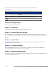
PREFACE This preface describes the audience, use, and organization of the Management and Configuration Guide. It also outlines the document conventions, safety advisories, compliance information, related documentation, support information, and revision history. Audience The primary audience for this document are network administrators who want to enable their network users to communicate using the ProCurve system.
-
The following notices and icons are used to alert you to important information. Table 2. Notices Icon Notice Type Alerts you to... None Note Helpful suggestions or information of special importance in certain situations. None Caution Risk of system functionality loss or data loss. Warning Risk of personal injury, system damage, or irrecoverable data loss.
-
Chapter 6—“Configuring the Network” This chapter describes how to configure the 700wl Series system components so that they work with your enterprise network. Chapter 7—“Setting up Wireless Data Privacy” This chapter describes how to enforce security using IPSec, L2TP, and PPTP. Chapter 8—“System Maintenance” This chapter explains how to install new software, backup your system, and shutdown and reboot. Chapter 9—“Logs” This chapter explains how to configure, examine and use the 700wl Series system log.
-
“Index of Commands” The Index of Commands is an alphabetized list of the CLI commands with references to the pages where they are documented. Related Publications There are several other publications related to the 700wl Series that may be useful: • 700wl Series Software Release Notes provides the most up-to-date information on the current software release.
-
INTRODUCTION 1 This chapter provides a brief introduction to the 700wl Series system™ and its primary features. The topics covered in this chapter include: 700wl Series Overview . . . . . . . . . . . . . . . . . . . . . . . . . . . . . . . . . . . . . . . . . . . . . . . . . . . . . . . 1-1 700wl Series Functions . . . . . . . . . . . . . . . . . . . . . . . . . . . . . . . . . . . . . . . . . . . . . . . . . . . . . . .
-
Introduction Figure 1-1 illustrates a 700wl Series system topology that is configured with redundant Access Control Servers for failover. Figure 1-1. 700wl Series topology Access Control Server Redundant Access Control Server Internet Access Controller xl Module Guest Guest Untrusted User Employee Access Controller Untrusted User Employee Access Controllers sit at or near the edge of the network, and enforce authentication and access policies.
-
Introduction encryption requirements. Access Policies can be configured to “expire” after a specified length of time, or at a specific time, forcing the client to reauthenticate. Clients that are successfully authenticated, such as the Employees in Figure 1-1, are typically associated with Access Policies that provide access to secure network resources.
-
Introduction The 700wl Series system supports the following authentication services, any of which can be used in an Authentication Policy: • LDAP directory services, such as Active Directory or iPlanet LDAP server • RADIUS servers • Kerberos services • XML-RPC-based services • The Rights Manager’s built-in database. This is the default authentication service. You can populate it with user names and passwords through the Rights Manager.
-
Introduction Roaming Support One of the key features of the 700wl Series system is its support of layer 3 roaming—enabling clients to move around physically between access points without having to reauthenticate or establish a new session. Because the 700wl Series system identifies clients by MAC address, it is simple to detect when a device roams.
-
Introduction To allow flexibility, the 700wl Series system provides alternate addressing schemes: • Use NAT only if the client’s IP address is on the wrong subnet, that is specifically not within the Access Controller’s subnet. Otherwise, use the client’s real or static IP address. • Always use the client’s real or static IP address and never use NAT, regardless of the subnet. This setting is intended for access points, and should be used with caution.
-
Introduction After a packet has been marked with a priority setting it becomes accessible for QoS handling on the network. Ingress packets with VLAN tags can retain their 802.1p settings while their VLAN ID is replaced. This includes packets with a VLAN ID of zero (0) also called the null VLAN ID. Just like the VLAN support feature, VLAN tags can be removed, replaced, or retained. The VLAN ID and 802.1p priority settings will not be overwritten by the VLAN settings in an Access Policy.
-
Introduction 1-8 ProCurve Secure Access 700wl Series Management and Configuration Guide
-
USING THE 700Wl SERIES SYSTEM 2 This chapter provides a brief introduction on using the 700wl Series system and its Administrative Interface. It also provides an overview and discussion on a number of common tasks you may need to accomplish. The topics covered in this chapter include: Initial Configuration of the 700wl Series System . . . . . . . . . . . . . . . . . . . . . . . . . . . . . . . . . 2-1 Managing and Administering the 700wl Series System . . . . . . . . . . . . . . . . . . . . . . . . . .
-
Using the 700wl Series System able to communicate with the 700wl Series system until this is set, so it is recommended that you do it as part of the initial installation. For an Access Controller, the initial settings include: • IP address of the Access Controller • Subnet mask that defines the subnet associated with the Access Controller (the default is 255.255.255.
-
Using the 700wl Series System users, creating or modifying Access Policies, modifying the Rights Table, setting up Authentication Services or Authentication Policies, or other similar functions. A Network Administrator can view all the pages in the Status and Logs areas.
-
Using the 700wl Series System • Set up Authentication Policies that determine how clients authenticate themselves to the system • Set up Access Policies to control what users can do over the network • Set up Identity Profiles to put users in groups that share the same access policies • Customize login pages Logging on to the Administrative Interface To monitor or configure the 700wl Series system you use the Administrative Interface. This is a webbased interface.
-
Using the 700wl Series System Changing the Built-In Administrator Settings To change the built-in administrator name and password on a700wl Series system unit, do the following: Step 1. Click the Network button in the Navigation bar. The System Components page appears, with a System Components List that shows the components that make up your 700wl Series system. Step 2. Click a system component name listed under the Component Name heading to bring up the Edit page. Step 3.
-
Using the 700wl Series System — Related Topics links: these are presented at the top of the page, or they can be accessed from a Related Topics menu displayed using the Related Topics button — Table of Contents and Index, accessed through the navigation panel at the left of the page. — You can display the Table of Contents by clicking the Contents button You can also print the page you are viewing by clicking the print button • .
-
Using the 700wl Series System The various pages of the Administrative Interface have many elements in common, as well as elements specific to certain pages.
-
Using the 700wl Series System Figure 2-4. Header and Navigation Bars for a Secondary Access Control Server The Navigation bar is always accessible from anywhere in the Administrative Interface. Each Navigation button takes you to a set of pages related to specific administrative functions. Status The Status pages of the Administrative Interface provide views of the status of system equipment, clients, and sessions.
-
Using the 700wl Series System Logs The Logs pages provide views of the log data, which includes time, source, severity and event description. Log data can be filtered and exported as text files. Configure the settings for a syslog server for traffic and client session analysis. These pages are available to administrators of all access levels. For details, refer to Chapter 9, “Logs”. Help Click this button in the Navigation bar to view context-sensitive HTML help for the tab or subordinate tab displayed.
-
Using the 700wl Series System Some tabs represent complex sets of functions. These may use sub-tabs to further organize the functions and make them easier to use. Sub-tabs work the same as tabs, with the active tab shown in white and inactive tabs grayed out. When there are action buttons, for example the Save button ( ), displayed at the bottom of the page, the buttons pertain to the entire set of functions available under the tab.
-
Using the 700wl Series System In a redundant configuration, both Access Control Servers are shown in the System Components List. However, you cannot make configuration changes to the secondary Access Control Server from the Administrative Interface on the primary Access Control Server, and vice versa. You must logon to the Administrative Interface of the peer Access Control Server to make changes to it.
-
Using the 700wl Series System Figure 2-7. Display Filters and Auto Refresh Settings Display Filter Options Select the desired filter values using the drop-down lists and click Apply Filters to refresh the display with data that matches the filter criteria. On the Log Files page, a Search capability is also provided to allow you to search for a particular string in a log file message. See Figure 2-7.
-
Using the 700wl Series System Figure 2-8. Configure Tables • Manipulating rows To operate on rows in a table, use the buttons on the right side of the row as shown in Figure 2-8. The common buttons for editing an item ( ) and for deleting an item ( ) are shown. See “Common Buttons” on page 2-15 for a full list of buttons. • Manipulating items within a row In some tables you can edit an item in the table by clicking on that item.
-
Using the 700wl Series System Clicking the column heading sorts the table based on the alphabetical ordering of the items in that column. Clicking the first time, sorts the column in ascending order; clicking a second time reverses the sort order. The column that is currently determining the display order is indicated by showing the heading cell with a darker grey background. In Figure 2-9 the display is ordered based on the Time column.
-
Using the 700wl Series System Common Buttons The following table lists the common buttons used in the Administrative Interface and gives their meaning. Button Function Folder: This represents a user-defined folder for system components. Folders can be opened, revealing their contents, by clicking on the open folder button ( ). They can be closed by clicking on the close folder button ( ). This button appears in the System Components List. See the example in Figure 2-5.
-
Using the 700wl Series System • If you want to upgrade the 700wl Series system software, read “Updating the System Software” in Chapter 8, “System Maintenance”. Setting Up Authentication and Access Rights Chapter 4, “Configuring Rights” and Chapter 5, “Configuring Authentication” explain the Rights Manager and should be read together since access rights and authentication are closely related.
-
Using the 700wl Series System As soon as an Access Controller is configured to communicate with its Access Control Server, that Access Controller will appear in the System Components List on the Access Control Server. By selecting the Access Controller in this list you can perform configuration and management functions such as setting the date and time, configuring options such as bridging, port subnets, SNMP access, and so on.
-
Using the 700wl Series System will keep the secondary Access Control Server synchronized with the primary Access Control Server. A “heartbeat” message between the primary and secondary is used to keep the secondary Access Control Server informed that the primary is functioning. The communication between the two peer Access Control Servers is done via a proprietary message based protocol over TCP/IP. Upon restart, an Access Controller attempts to communicate with the primary Access Control Server.
-
Using the 700wl Series System When connectivity is restored, the Access Control Servers will again exchange heartbeat messages and the preferred primary will reclaim its role as the primary Access Control Server.
-
Using the 700wl Series System force for that client. This implementation does not attempt to shape bandwidth usage, just enforce a perclient cap. Because bandwidth limits are set in the Access Policy, you can set different limits for different sets of clients even if they are connecting through the same physical port.
-
Using the 700wl Series System Addressing in the 700wl Series System Clients connected to Access Controller or Integrated Access Manager ports can obtain an IP address in one of three ways: • Network Address Translation (NAT) mode: The Access Controller (or Integrated Access Manager) responds to a DHCP request from a client with a “private” IP address in the subnet configured for NAT (by default, the 42.0.0.1 subnet).
-
Using the 700wl Series System but when the client’s DHCP lease expires, it might successfully get a valid real IP address, which would be used as the source IP instead of a NAT address. • If NAT is never allowed (the Access Policy NAT setting is Never) the Access Controller or Integrated Access Manager always uses the client’s real IP address (as obtained via DHCP) or its static IP address.
-
Using the 700wl Series System • The inner tunnel address is assigned per the Access Policy NAT setting, as discussed above. However, if Real IP mode is used, the client’s IP address is assigned as specified through the Tunneling Configuration page—either via the external DHCP service or from a specified address range.
-
Using the 700wl Series System VLANs and the 700wl Series System The following discussion assumes that you have read Chapter 4, “Configuring Rights” and are familiar with Connection Profiles, Access Policies, and how rights are assigned to a client in the 700wl Series system. The HP System provides support for Virtual LAN (VLAN) tagging in several ways: • VLAN IDs (802.1Q tags) can be associated with uplink subnets on each Access Controller.
-
Using the 700wl Series System Authenticated clients with VLAN 20 tag will match the first row in the table, and will receive access rights based on the Access Policy created for members of that VLAN (VLAN20clientRights). Authenticated clients in VLAN 10 will match the second row, and receive access rights accordingly. The Access Policies associated with the VLAN-specific Connection Profiles can be configured to modify the VLAN tagging of these clients, if necessary.
-
Using the 700wl Series System classification can be based on a variety of other criteria, including VLAN ID, IP protocol, source and destination IP addresses and ports, MAC address, user identity, slot/port combination, and Ethertype. After a packet has been marked with a priority setting it becomes accessible for QoS handling on the network. Ingress packets with VLAN tags can retain their 802.1p settings while their VLAN ID is replaced.
-
SYSTEM STATUS 3 This chapter explains how to view the system status tables of the 700wl Series system. You can view the status of any and all system equipment (Access Controllers and Access Control Servers), clients (users, identified either by username and password or by MAC address), and sessions. You can view all the status information from one central location.The topics covered in this chapter are: Viewing Status Information . . . . . . . . . . . . . . . . . . . . . . . . . . . . . . . . . . . . . .
-
System Status Figure 3-1. Getting to Status Information There are four tabs in the status module: • Equipment Status presents an overview of the status of the Access Control Servers and Access Controllers. From this page you can view a more detailed status for each Access Controller. • Client Status presents a list of clients currently connected to the 700wl Series system through the connected Access Controllers.
-
System Status in the Equipment Status table by expanding or closing folders in the list to display only the Access Controllers of interest. If a display has more entries than will fit on one page (based on the Rows per Page filter setting), page navigation controls are enabled to let you navigate between the results pages. In the Client Status and Session Status views, you can sort the display by the data in any column.
-
System Status Viewing Access Control Server Status The Access Control Server status table, as shown in Figure 3-3, shows the following information: Table 3-1. Access Control Server status Row Description (Primary/Secondary) Access Control Server Status of the Access Control Server whose Administrative Interface you are currently logged into.
-
System Status Figure 3-3. Access Control Server status table in a redundant configuration Viewing Access Controller Status The Access Controller status table displays the following information about each Access Controller: Table 3-2. Active Access Controllers Display Column Description Component Name The name assigned to the Access Controller, see “Configuring Access Controllers” on page 6-10. Click on the Component Name to view the status details for the Access Controller.
-
System Status Table 3-3. Access Controller Detail Page: System Inventory Display » » Column Description Equipment The name of the Access Controller. By default, the IP address appears as the name if the name has not been changed. IP Address The IP address of the Access Controller. System ID The System ID is the MAC address of the reserved port on a 700wl Series unit. On a 700wl Series unit, the System ID is the MAC address of the uplink port.
-
System Status » To refresh the rights for a specific user, click the refresh user rights icon ( the user is in. » » To refresh the user rights for all clients on the Access Controller, click Refresh User Rights Now. ) on the far right of the row To look at the status details for a client, click the client name (either a logon name or an IP address) in the left column of the client status table. See “Viewing Client Details” on page 3-8 for more information.
-
System Status By default Status page data is refreshed only when you click Apply Filters. You can set the page to automatically refresh the data at specified intervals. » To set the page to refresh the data at specified intervals, select the desired refresh interval from the drop down list of possible refresh rates (or select Auto Refresh Off to disable this) and click Apply Filters. Table 3-5 shows the Client status filtering options you can use to filter the Client status display: Table 3-5.
-
System Status Table 3-6. Active Client detail information Information Description IP Address The IP address assigned to the client. If the client is connected using PPTP or L2TP, this is the inside tunnel address. The outside tunnel address is also listed (“via tunnel from “). See “IP Address Assignment for Tunneling” on page 7-11 for more information on Address Tunneling. Address Status Information about the IP address. This includes: • Whether NAT mode is being used, and why.
-
System Status Viewing Session Status Viewing session status provides information on a client’s open sessions and network traffic. » To view active sessions, click the Session Status tab. The View Active Sessions page appears. » » » To filter the session data, select the desired filters and click Apply Filters. » To go to different pages of the session status table, use the page navigation controls at the bottom of the page on the left.
-
System Status » To filter a display, select the filtering parameters from the filter drop down lists in the left panel of the status page and click Apply Filters. This refreshes the display with the status results based on the filtering parameters you have set. By default Status page data is refreshed only when you click Apply Filters. You can set the page to automatically refresh the data at specified intervals.
-
System Status 3-12 ProCurve Secure Access 700wl Series Management and Configuration Guide
-
CONFIGURING RIGHTS 4 This chapter describes how network access rights are assigned to clients through the 700wl Series system, and explains how to configure access control policies. The topics covered in this chapter include: Access Rights in the 700wl Series System . . . . . . . . . . . . . . . . . . . . . . . . . . . . . . . . . . . . . . . 4-2 The Rights Manager . . . . . . . . . . . . . . . . . . . . . . . . . . . . . . . . . . . . . . . . . . . . . . . . . . . . . . . . .
-
Configuring Rights Access Rights in the 700wl Series System The 700wl Series system allows network administrators to define highly flexible access control policies that grant network access to a client based on who the client is, where they connect to the 700wl Series system, and the time of day when they make the connection. The 700wl Series system uses a client’s identity (user name or MAC address) to match the client to an Identity Profile.
-
Configuring Rights “Authenticated” profile in the default case). It is granted a new set of rights based on the Access Policy in the row that matches the client’s new Identity Profile and Connection Profile. If the client roams such that its wireless connection moves to a port in a different Connection Profile, a new table search occurs, and the client will match a different row in the Rights Assignment Table, based on the combination of the same Identity Profile but a different Connection Profile.
-
Configuring Rights automatically matches “Any.” The “Any” Connection Profile always appears in the last row of the Rights Assignment Table. Connection Profiles are used in two ways in the 700wl Series system: — The Connection Profile is also used to determine the method by which an unknown (unauthenticated) client should be authenticated. This is discussed later in “Authentication in the 700wl Series System” on page 5-1.
-
Configuring Rights • Allowed Traffic Filters and Redirected Traffic Filters. These may be used when defining Access Policies. These also include the special case of WINS and DNS filters, which are created through a separate interface and result in matched Allowed and Redirected traffic filter pairs. • HTTP proxy servers and proxy filters. These also may be used when defining Access Policies.
-
Configuring Rights Due to Access Point coverage overlap, Locations may not behave quite as expected if your Access Points are in close proximity. For example, if you have one Access Point connected to a port defined as Location Marketing, and a nearby Access Point defined as Location Engineering, a single, stationary user may be connected through the Marketing Location in one instance, and through the Engineering Location the next time.
-
Configuring Rights Step 4. Add rows to the Rights Assignment Table by combining the Identity Profiles, Connection Profiles and Access Policies you’ve created. The order of these rows in the table is important, as whenever the 700wl Series system looks for a match it searches the table row by row starting from the top, and stops when it find the first match.
-
Configuring Rights and password will be passed on for authentication based on the Authentication profile associated with the Connection Profile. This means that an unknown client that matches on row 5 might be authenticated differently from a client that matches row 6. (Authentication is discussed in more detail in “Authentication in the 700wl Series System” on page 5-1.
-
Configuring Rights Like Guests, clients identified only by MAC address are not considered authenticated, and therefore do not match the “Authenticated” Identity Profile. If a MAC address user has been added to the built-in database, but has not been assigned to an Identity Profile, that client will continue to match the “Any” Identity Profile. Note: It is important that rows with the “Access Points” Identity Profile appear in the table before rows that contain the “Any” Identity Profile.
-
Configuring Rights Identity Profiles Identity Profiles represent named groups of users or equipment that have some characteristic in common—usually a common need for a certain set of access rights. An Identity Profile can be populated with user or network equipment entries from the built-in database, or it can represent an external group or domain. In the latter case, the Identity Profile does not need to have any specific Users or equipment associated with it.
-
Configuring Rights » To create a new Identity Profile, click the New Identity Profile button at the bottom of the Identity Profiles list. This takes you to the New Identity Profile page. You can use the links directly under the page name in the left-hand panel of the page to go directly to the Users or Network Equipment pages to view lists of users and network equipment in the built-in database.
-
Configuring Rights Figure 4-5. Creating a New Identity Profile, with User list displayed From this page, with the Users or Network Equipment list displayed, you can also add a new user or equipment item, or edit a user or equipment item. See “Users in the Built-In Database” on page 4-13 and “Network Equipment in the Built-in Database” on page 4-17 for details on these functions. To create a new Identity Profile: Step 1. Enter a name for the Identity Profile in the Name field.
-
Configuring Rights getting rights based on matching this Identity Profile in the Rights Table. It is possible that the user could still get a set of rights based on matching a different Identity Profile. When the concurrent logon limit is reached, the next client to log on using that username and password is still authenticated successfully, since the username and password are presumably still valid.
-
Configuring Rights The built-in database can have other uses as well. If you want to pre-register Guest users, you can do so by adding them to the built-in database. You can also streamline the authentication process for selected users by adding them to the built-in database as MAC address users. This mechanism lets them bypass the normal external authentication process, and get the appropriate set of access rights immediately when they connect to the system.
-
Configuring Rights » To export the entire list of users to file, use Export as Text. The list is displayed in a new browser window. Select File->Save As from the browser menu. The Save As dialog box appears. Select the file location and file type, type the file name and click Save.
-
Configuring Rights The fields on this page are as follows: Table 4-2. New User Fields Field Description Name A descriptive name that identifies the user in the 700wl Series system’s Administrative Interface. This is the name that appears in Client Status display, among others. It can be the user’s full name or any other meaningful name. This name may have up to 32 characters. Any 7-bit characters are allowed. Username/MAC Address The user’s username (logon ID) or MAC address.
-
Configuring Rights will not have the opportunity to log on and provide a username. That client will then not match an Identity Profile based on its username, but rather will receive rights based on its MAC address. Step 2. Select the Identity Profile to which this user should be assigned by clicking the appropriate check box in the Identity Profiles table. As a rule, you would assign a user to only one Identity Profile, since the search for a match always stops at the first match found.
-
Configuring Rights other network devices do not necessarily need to have access rights of their own in order to function correctly in the system, however, if you want to manage these devices from within the 700wl Series system, you may want to assign them a specific set of access rights. You can add these devices to the built-in database and assign them to an Identity Profile so that they can get rights assigned through the Rights Assignment Table.
-
Configuring Rights From the Network Equipment page you can also go directly to the Identity Profiles page or to the Users page by clicking the link near the top of the left-hand column, just below the page name. Creating or Editing an Equipment Entry To create a new network equipment entry, click New Network Equipment at the bottom of the Network Equipment list. The New Network Equipment page appears, as shown in Figure 4-7, with empty fields and no Identity Profile selected.
-
Configuring Rights Table 4-4. New Network Equipment Fields Field Description MAC Address The MAC address of the network device. A MAC address can be entered with colons (:) or dashes (-) separating the tuples, or without any separation. Thus, 00:01:a2:b3:4c:d5, 00-01-a2-b3-4c-d5, and 0001a2b34cd5 are all valid formats for a MAC address. A MAC address can be entered with colons (:) or dashes (-) separating the tuples, or without any separation.
-
Configuring Rights » When you have finished, click Save. This replaces the original equipment entry with the modified information. Click Cancel to return to the previous page without making any further changes. Retrieving MAC Addresses from an LDAP Database The 700wl Series system’s built-in database can be used to keep the MAC addresses of Access Points and other client devices that cannot be authenticated using a user ID and password.
-
Configuring Rights Group membership can be retrieved in one of two ways: • If the LDAP database contains individual records for each MAC address user, an attribute in those records can define the groups to which the MAC address belongs. • Records can be used to represent groups, each of which contains a set of MAC addresses that are members of that group. Specifying an LDAP Service for MAC Address Retrieval To set up MAC address retrieval from an LDAP service, do the following: Step 1.
-
Configuring Rights » To download MAC addresses from a specific LDAP database, click the download icon at the end of the row. This does an immediate download from this individual database. You can do this even if you have configured MAC Address Retrieval to happen automatically at set intervals. If you have not configured the service for MAC address retrieval, attempting to download produces an error.
-
Configuring Rights Table 4-5. Configuring MAC Address Retrieval, address retrieval parameters Field Description MAC Address Attribute The name of the attribute in the record that contains the individual MAC addresses, for example, uniquemember. Instances of this attribute should contain the MAC addresses that are to be added to the built-in database.
-
Configuring Rights Retrieving Group Identity Information from MAC Address User Records Suppose, for each MAC address, an entry exists with attributes similar to the following: dn: cn=000122034a5b, o=XYZCorp, c=us cn: 000122034a5b, o=XYZCorp, c=us sn: 000122034a5b mymember: Contractors mymember: DBSpec Then, do the following: Step 1. Select Search for MAC Addresses using attribute found in the initial search.
-
Configuring Rights Connection Profiles A client is associated with a Connection Profile based on the Access Controller port through which he accesses the 700wl Series system, the VLAN to which he belongs (if any) and the day, date and time that he accesses the system. The default Connection Profile, “Any” includes clients from any Access Controller port, belonging to any VLAN or no VLAN, at any time, on any day.
-
Configuring Rights Table 4-7. Connection Profiles Table Contents Column Description Logon Page The Logon page that should be presented to an unknown client that matches this Connection Profile, if the Authentication Policy associated with this Connection Profile uses a browser-based logon page. Authentication The Authentication Policy that applies to unknown clients that match this Connection Profile.
-
Configuring Rights Figure 4-13. Creating a New Connection Profile, the Settings Tab To create or edit a Connection Profile, do the following: Step 1. Type a name for a new Connection Profile. You can change the name of an existing Connection Profile by typing a new name. Step 2. On the Settings tab, select or enter data into the fields as described in Table 4-8 below. The fields under the Settings tab are as follows: Table 4-8.
-
Configuring Rights Table 4-8. New Connection Profile Settings Tab Contents Column Description VLAN Identifier How an 802.
-
Configuring Rights The Locations tab shows a list of the currently defined Locations. The columns in this list are as follows: Table 4-9. Locations Tab Column Definitions Column Description Name The descriptive name for the Location. Details The definition of the Access Controllers and ports, or the client’s MAC address, included in the Location. • To select all Locations in the list, select the check box next to the Locations column heading.
-
Configuring Rights • To select all Time Windows in the list, select the check box next to the Locations column heading. Clicking this check box a second time removes the checks from all Time Windows in the list. • To remove a Time Window from the profile, click its check box to remove the check. Step 5. Click Save to save this Connection Profile. If you are editing a Connection Profile, this replaces the original Connection Profile with the modified Connection Profile definition.
-
Configuring Rights » To create a new Location, click the New Location button at the bottom of the Locations list. This takes you to the New Location page (see “Creating or Editing a Location”). From this page you can also go directly to the Connection Profiles or Time Windows pages using the links directly under the page name in the left-hand panel of the page. See “Connection Profiles” on page 4-26 and “Time Windows” on page 4-33 for details on these functions.
-
Configuring Rights Time Windows A Time Window is a specification of a period of time, defined by specific dates or date ranges, days of the week, and hours of the day. Time Windows may be used to limit when a Connection Profile is available as a valid match for a client.
-
Configuring Rights The Edit Time Window page is almost identical to the New Time Window page, except that the name and port selections are displayed for the Time Window you have selected, and a Save As Copy button is available. Figure 4-19. Adding a New Time Window To create or edit a Time Window, do the following: Step 1. Type a name for this Time Window in the Name field. You can change the name of an existing Time Window by typing a new name. Step 2.
-
Configuring Rights You can combine all three settings to create a specific Time Window. For example, you could specify a Time Window that’s valid on Mondays, Wednesdays, and Fridays from 11:00 am until 2:00 pm, between June 1, 2003 and September 15, 2003. Step 3. Click Save to save this Time Window. If you are editing an existing Time Window, this replaces the original Time Window with the modified Time Window definition.
-
Configuring Rights Figure 4-20. Access Policies Page The 700wl Series system provides five predefined Access Policies, and a Rights Administrator can create additional ones. The predefined Access Policies are: • Authenticated: This defines a default set of rights for users that have been successfully authenticated. • Guest Access: This defines a default set of rights for users that have logged on using the “Logon as a Guest” feature.
-
Configuring Rights Table 4-14. Access Policies Table Contents Column Description Allowed Traffic | Grid A list of the Allowed Traffic Filters selected for the Access Policy. Click Grid in the column heading to display all Access Policies and Allowed Traffic Filters in a grid format. See “The Allowed Traffic Filters Grid” below for an explanation of that display format. See “Creating or Editing an Allowed Traffic Filter” on page 4-68 for information about defining Allowed Traffic Filters.
-
Configuring Rights Figure 4-21. Access Policies and Allowed Traffic Filters in a Grid Format Each row represents an Access Policy. The Allowed Traffic Filters are shown in columns. Filters that are enabled for the Access Policy are represented by checks in the appropriate column check box. This format makes it easy to compare which filters are enabled for different Access Policies. » To edit an Access Policy, click the Access Policy name.
-
Configuring Rights Figure 4-22. Access Policies and Redirected Traffic Filters in a Grid Format Each row represents an Access Policy. The Redirected Traffic Filters are shown in columns. Filters that are enabled for the Access Policy are represented by checks in the appropriate column check box. This format makes it easy to compare which filters are enabled for different Access Policies.
-
Configuring Rights Figure 4-23. Creating a New Access Policy, the Settings Tab To create or edit an Access Policy, Step 1. Type a name for the policy in the Name field. You can change the name of an existing Access Policy by typing a new name. Step 2. Select settings or enter data on each of the tabs as appropriate. See the sections below for a detailed discussion of each tab. Step 3. Click Save to save this Access Policy.
-
Configuring Rights To have your changes affect currently connected clients, you must go to either the Rights Setup page or the Client Status page and click Refresh User Rights Now. Otherwise, any changes you make take effect the next time a client gets new rights. Changes do not automatically affect connected clients. Note: The Settings Tab On the Settings tab, select or enter data into the fields as described in Table 4-15 below. The fields under the Settings tab are as follows: Table 4-15.
-
Configuring Rights Table 4-15. New Access Policy Settings Tab Contents Column Description Encryption Whether encryption is required, allowed, or disabled: • Select Disabled to disable encryption for clients associated with this Access Policy. (This is the default.) • Select Allowed, but not required to allow both encrypted and non-encrypted traffic from clients associated with this Access Policy. The Encryption Protocols settings determine the type of encryption allowed.
-
Configuring Rights Table 4-15. New Access Policy Settings Tab Contents Column Description Authentication Method For L2TP or PPTP, the method that should be used to authenticate users who connect and present a username and password via an L2TP or PPTP client: • Select Use Associated Authentication Policy to use the Authentication Policy associated with the Connection Profile associated with this Access Policy.
-
Configuring Rights If the IP address is not valid, the Access Controller assigns a private IP address and rewrites the source address in packets. With this setting it is possible that a client might receive a NAT’ed address initially, but when the client’s DHCP lease expires, it might successfully get a valid real IP address, which would be used as the source IP instead of a NAT’ed address.
-
Configuring Rights Whether you are creating a new Access Policy or editing an existing Access Policy, all QoS Markings that are currently defined in the 700wl Series system will be listed. If you are creating a new Access Policy, the QoS Markings are displayed in alphabetical order. If you are editing an Access Policy, the QoS Markings that are included in this Access Policy are displayed at the top of the list, and the QoS Markings not included are at the bottom of the list.
-
Configuring Rights See “Creating or Editing a QoS Marking” on page 4-62 for instructions on the New QoS Marking and Edit QoS Marking pages. The Allowed Traffic Tab Allowed Traffic filters are traffic filters that identify packets that are permitted to be forwarded by an Access Controller. If you are creating a new Access Policy, the Allowed Traffic filters are displayed in alphabetical order.
-
Configuring Rights Figure 4-25. Creating an Access Policy, the Allowed Filters Tab Note that if the filter you select is one of a DNS or WINS filter pair, you must also include the corresponding Redirected Traffic member of the pair in your Access Policy, to redirect traffic to the proper DNS or WINS server.
-
Configuring Rights The Allowed Traffic list shows all existing Allowed Traffic filters. These are displayed in alphabetical order if you are creating a new Access Policy. If you are editing an Access Policy, the filters included in the policy are displayed at the top of the list. The following information is provided about each filter: Table 4-17. Allowed Traffic List Definitions » » » Column Description Name The name for the Allowed Traffic Filter. Details The optional description of the filter.
-
Configuring Rights Table 4-18. Predefined Allowed Traffic Filters (Continued) Allowed Traffic Filter Description Internal rights UI Allows access to the Rights Manager pages via the Access Controller defined in @INTERNAL@ (by default 42.0.0.
-
Configuring Rights Figure 4-26. Creating an Access Policy, the Redirected Traffic Tab The Redirected Traffic list shows the following information about each filter: Table 4-19. Redirected Traffic List Definitions » » Column Description Name The name for the Redirected Traffic Filter. Details The optional description of the filter. To select a filter to include in this Access Policy, click the appropriate check box.
-
Configuring Rights appropriate destination. Therefore, an incorrect ordering of Redirect filters could cause some filters never to be evaluated. For example, if a more general filter is evaluated before a more specific filter, packets could be redirected due to matching the general filter, and never be evaluated by the more specific filter. Reordering the filter list affects only the Access Policy that is currently being created. Each Access Policy may use a different ordering of Redirect filters.
-
Configuring Rights Table 4-20. Predefined Redirected Traffic Filters (Continued) Redirected Traffic Filter Description SOCKS redirect Redirects all SOCKS requests to the Access Controller If these filters are not sufficient to meet your needs, you can create your own filters. See “Creating or Editing a Redirected Traffic Filter” on page 4-71 for instructions.
-
Configuring Rights If an IP address and port is configured for HTTP proxy in both an Access Policy and on an Access Controller, the Access Policy configuration takes precedence and HTTP traffic for that Access Policy will be directed to the external HTTP proxy server.
-
Configuring Rights External HTTP Proxy Server Specified in the Access Policy Specifying an HTTP proxy server in an Access Policy allows finer grain control of which class of users use which HTTP proxy servers. All HTTP traffic is redirected to the externally configured HTTP proxy server associated with the Access Policy without being passed through the internal HTTP proxy server on the Access Controller.
-
Configuring Rights To configure the HTTP Proxy feature for anAccess Policy, select the HTTP Proxy tab, as shown in Figure 4-27, and select or enter the data into the fields as described in Table 4-22. Figure 4-27. Creating an Access Policy, the HTTP Proxy Tab The fields under the HTTP Proxy tab are as follows: Table 4-22. HTTP Proxy Tab Field Definitions Field/Column Description Automatic HTTP Proxy Enables or disables automatic HTTP proxy filtering for this Access Policy.
-
Configuring Rights Table 4-22. HTTP Proxy Tab Field Definitions (Continued) Field/Column Description Filter The filter type. The choices are: • Allow IP Accept HTTP traffic destined for the specified IP address • Allow FQDN Accept HTTP traffic destined for the specified fully-qualified domain name (e.g. www.domain.com) • Allow Host Accept HTTP traffic destined for the specified host name (e.g.
-
Configuring Rights • To create a new filter, click New Filter. The New Filters page appears. See “Creating or Editing an HTTP Proxy Filter” on page 4-80 for more information. The Bandwidth Tab 700wl Series system provides the ability to limit the bandwidth available to each client to prevent network performance degradation. Using Access Policies, bandwidth can be limited on a client by client basis. Separate limits can be set for upstream and downstream bandwidth.
-
Configuring Rights currently in force for that client. This implementation does not attempt to shape bandwidth usage, just enforces a per-client cap. Because bandwidth limits are set in the Access Policy, you can set different limits for different sets of clients even if they are connecting through the same physical port.
-
Configuring Rights The Linger Timeout The Linger timeout enables the 700wl Series system to force a logoff for clients that have disconnected from the network without logging off. If the Access Controller determines that a client has been nonresponsive for a specified period of time, the Access Controller sends a disassociate message to the Access Control Server, following which the Linger Timeout starts.
-
Configuring Rights Figure 4-29. Creating an Access Policy, the Timeout Tab The fields under the Timeout tab are as follows: Table 4-24. Timeout Tab Field Definitions Field Description Linger Timeout How long a client remains known to the 700wl Series system after being disassociated from an Access Controller for failing to respond to repeated polls (ARPs). • Enter the number of seconds the system should wait before logging off the client from the system.
-
Configuring Rights QoS Markings QoS Markings classify and mark client traffic based on a variety of criteria. For more information about the different criteria and marking available for traffic classification, see “Creating or Editing a QoS Marking”. Whether you are creating a new Access Policy or editing an existing Access Policy, all QoS Markings that are currently defined in the 700wl Series system will be listed.
-
Configuring Rights Creating or Editing a QoS Marking QoS Markings can be used for classification and marking of ingress packets for QoS processing to your network. See “QoS Marking” on page 2-25 for more general information about this feature. Ingress packet priority settings can be retained, mapped to different priority settings, or in the case of 802.1Q/p, removed. Client packets can be marked based on 802.1p, DiffServ, IP Precedence, and ToS standards.
-
Configuring Rights Figure 4-31. Creating a New QoS Marking The fields in both the New QoS Marking and Edit QoS Marking page are briefly described in Table 4-26. For more in depth descriptions see the instructional steps in this section. Table 4-26. QoS Marking Field Definitions Category Field Description Marking Criterion Name A descriptive name for this QoS Marking. Description A description of this QoS Marking.
-
Configuring Rights Table 4-26. QoS Marking Field Definitions (Continued) Category Field Description QoS Markings DiffServ If DiffServ is selected, the DS Codepoint must be specified for marking any ingress packets that match the specified criterion. Valid entries are from 0 to 63. IP (ToS) If IP (ToS) is selected, either the Precedence or the Type of Service must be specified for marking any ingress packets. Valid entries are from 0 to 15 for IP ToS, and 0 to 7 for Precedence.
-
Configuring Rights Table 4-27. Marking Type Field (Continued) d. Criterion Type Criterion Values Description Ingress DS codepoint 0-63 DiffServ codepoint (RFC2474) uses six bits of the DiffServ field, which was the ToS byte. Generally, the lower number has lower priority and higher number has higher priority. Client MAC address Valid MAC string The MAC address of the device sending ingress packets.
-
Configuring Rights • To replace an 802.1p priority setting, type the new priority setting in the Priority text box. • To remove both the VLAN ID and 802.1p priority settings, check the Remove check box. • To assign a VLAN ID and priority based on other packet classification specified in the Criterion fields, type the VLAN ID and 802.1p priority setting in the appropriate text boxes. Step 4. Click Save to save this QoS Marking.
-
Configuring Rights Figure 4-32. The Allowed Traffic Filters List The Allowed Traffic list shows the Allowed Traffic filters in alphabetical order, and includes the following information about each filter: Table 4-28. Allowed Traffic List Definitions Column Description Name The name for the Allowed Traffic Filter. Details The optional description of the filter. » To edit a filter, click the filter name in the Name column, or click the pencil icon at the end of the row.
-
Configuring Rights » To create a new filter, click the New Filter button at the bottom of the filter list. This takes you to the New Filter: Allowed Traffic page (see “Creating or Editing an Allowed Traffic Filter”). From this page you can also go directly to the Access Policies, QoS Markings, Redirected Traffic Filters, or HTTP Proxy Filters pages using the links directly under the page name in the left-hand panel of the page.
-
Configuring Rights Step 1. Type a name for this filter. You can change the name of an existing Allowed Traffic filter by typing a new name. Step 2. Type a description for the filter, or modify the existing description. Step 3. To specify the filter by selecting the protocol, and providing the port and destination IP address, select the Allow traffic via a specific protocol/port/address radio button. Then do the following: a.
-
Configuring Rights Redirected Traffic Filters Redirected Traffic filters are traffic filters that identify packets sent from a client that should be redirected to a new destination. Some Redirected Traffic filters may simply forward the packet to an alternate destination that performs the same function as the original destination—for example, a DNS server request could be redirected to the enterprise DNS server rather than the one that was originally specified.
-
Configuring Rights The Redirected Traffic list shows the Redirected Traffic filters in alphabetical order, and includes the following information about each filter: Table 4-29. Allowed Traffic List Definitions Column Description Name The name for the Redirected Traffic Filter. Details The optional description of the filter. » To edit a filter, click the filter name in the Name column, or click the pencil icon at the end of the row.
-
Configuring Rights Figure 4-35. Creating a New Redirected Traffic Filter You can create the filter specification in one of two ways: • Specify the traffic protocol, and the destination IP address and port, or • Define the filter as a regular expression in tcpdump syntax. This enables you to define complex filters. You specify the new destination by providing a port and IP address that the traffic should be redirected to. To create or edit a Redirected Traffic filter, do the following: Step 1.
-
Configuring Rights This displays in a separate pop-up window a list of ports for common destinations such as the Stop pages or the Logon pages. c. If you want to specify a destination IP address, type it in the Address field. The address field can be: — A single IP address — A network address (IP address plus netmask) — An asterisk (*) for any IP address — A built-in or user-defined Address variable An address can be preceded by a “!” or “not” followed by a space to negate the address.
-
Configuring Rights Built-in and User-defined Address Variables For use in both Allowed and Redirected Traffic Filters, the 700wl Series system provides a set of predefined address variables for various system components. These can be viewed (but not changed or deleted) in the Addresses tab of the pop-up window. User defined variables can be added, edited and deleted.
-
Configuring Rights Table 4-30. Predefined Address Variables Address Variable Value/Description @INTRANET@ The network address of the subnet on which the Access Control Server resides @LOGON_SERVER@ The IP address of the Logon Access Control Server. In a redundancy/failover configuration, this is always the IP address of the original primary Access Control Server, and remains so even when failover has occurred and the original Access Control Server is no longer functioning.
-
Configuring Rights Table 4-31. Edit Address fields Field Definition Value The value can be an IP address or host name, up to 255 characters in length. It can include the characters allowed for a fully-qualified host name—alphanumeric characters, period, dash, and slash. DNS/WINS Filter Pairs The DNS or WINS servers specified as part of the Basic Setup of each 700wl Series system component are used by the 700wl Series system for doing address resolution for its own needs.
-
Configuring Rights The Filter list shows the DNS or WINS filter pairs in alphabetical order, and includes the following information about each pair: Table 4-32. DNS or WINS Filter Pair list definitions » Column Description Name The name of the filter pair. Description The optional description of the filter pair. To edit a filter pair, click the filter pair name in the Name column, or click the pencil icon at the end of the row.
-
Configuring Rights Figure 4-39. Creating a New DNS Filter The first time you view one of these pages, the list of DNS or WINS servers will be empty. See Step 4 to manage the list of servers. To create or edit a DNS or WINS filter pair, do the following: Step 1. Type a name for this filter pair in the Name field. You can change the name of an existing filter by typing a new name. Note: The name you provide here is used for both the Allowed Traffic and Redirected Traffic members of the filter pair. Step 2.
-
Configuring Rights Step 4. In the bottom region of the page, you can manage the list of DNS or WINS servers you want to use for address resolution requests. Initially, this list is empty. Once you have added servers to the list, they remain in the list. a. To add a server to the list, type the IP address of the server in the field provided, and click Add Server.
-
Configuring Rights The HTTP Proxy list shows the HTTP Proxy filters in alphabetical order, and includes the following information about each filter: Table 4-33. HTTP Proxy Filter List Definitions Column Description Name The name for the HTTP Proxy Filter. Filter The type of filter. Details The optional description of the filter. » To edit a filter, click the filter name in the Name column, or click the pencil icon at the end of the row.
-
Configuring Rights Figure 4-41. Creating a New HTTP Proxy Filter To create or edit an HTTP Proxy filter, do the following: Step 1. Type a name for this filter in the Name field. You can change the name of an existing HTTP Proxy filter by typing a new name. Step 2. Type a description for the filter, or modify the existing description. Step 3. In the Proxy Filter field, select the rule type.
-
Configuring Rights Table 4-34. HTTP Proxy Filter Types Filter Rule Type Description • Deny Host Redirects HTTP traffic destined for a specified host name For example, www or home • Deny Net Redirects HTTP traffic destined for a specified network address (IP address and subnet mask) For example, 192.168.0.0/16 • Deny Reg Redirects HTTP traffic to a destination specified as a regular expression that evaluates to an address or address range. For example “(.*).domain.
-
Configuring Rights the network or to the Internet. If you want to allow guest users to have access to selected parts of your network, or to the Internet, you need to modify the Guest Access Policy. Enabling an Existing Allowed Traffic Filter—Outside World The simplest way to modify an Access Policy is to enable or disable an existing Allowed or Redirected Traffic filter.
-
Configuring Rights Figure 4-43. The Allowed Traffic filters for the Guest Access Policy Step 4. Find the row for the Outside World filter, as shown in Figure 4-43, and click the check box to select the filter. Step 5. Click Save to have this change take effect.
-
Configuring Rights Modifying the Outside World Filter to Restrict Access If the Outside World Allowed Traffic filter is not sufficiently restrictive for your network environment, you can modify it (or create a new filter) to restrict access to multiple subnets or IP addresses. Step 1. From the Allowed Traffic tab, click the Outside World filter. The Edit Filter page for Allowed Traffic appears, with the Outside World filter displayed. Step 2. To rename this filter, type a new name in the Name field.
-
Configuring Rights Step 6. If you have changed the Outside World filter, click Save to replace the current Outside World filter definition. To save this filter as a new filter, click Save as Copy. If you have created a new Allowed Traffic filter, make sure you enable it for the Guest Access Policy by selecting it under the Allowed Traffic tab for the Access Policy.
-
Configuring Rights Figure 4-45. Configuring Proxy Filters to limit access for the Guest Access Policy Step 3. Select Enabled from the drop-down list to enable the internal HTTP proxy server. (This takes effect when you Save the Proxy Filter definition.) Step 4. Enter the ports you want the 700wl Series system to monitor for HTTP traffic. Click Save. The Rights Setup page reappears. Step 5.
-
Configuring Rights HTTP Proxy filters could cause some filters never to be evaluated. In general, the most specific filters are evaluated first, then the more general filters. Step 8. Click Save to save the Access Policy with this set of Proxy filter specifications.
-
CONFIGURING AUTHENTICATION 5 This chapter describes how clients are authenticated through the 700wl Series system, and explains how to configure authentication policies. The topics covered in this chapter include: Authentication in the 700wl Series System . . . . . . . . . . . . . . . . . . . . . . . . . . . . . . . . . . . . . . 5-1 The Rights Manager . . . . . . . . . . . . . . . . . . . . . . . . . . . . . . . . . . . . . . . . . . . . . . . . . . . . . . . . . 5-4 Authentication Policies . . . . . . .
-
Configuring Authentication and the time window in which the connection exists. These, along with an optional VLAN tag specification, determine a Connection Profile for the client. The client’s identity (who the client is) is determined through the authentication process. This is used to assign an Identity Profile for the client. The combination of the Connection Profile and Identity Profile determine the Access Policy that applies to the client.
-
Configuring Authentication When the 700wl Series system receives a username and password from the logon page, the client is forwarded to the first authentication service in the list. If the first service fails to authenticate the client, the username and password is sent to the next service, and so on. If all services in the list fail to authenticate the user, then the user will continue to have only unauthenticated logon rights.
-
Configuring Authentication Wireless Data Privacy authentication methods may involve shared secrets or certificates, and the Authentication Policy associated with the Connection Profile is not necessarily used (the Encryption authentication may supersede it). — When used for authentication, SSH uses the Authentication Policy associated with the Connection Profile through which the user connected.
-
Configuring Authentication » To view the current Authentication Policies, click the Authentication Policies tab visible at the top of any Rights module page. The Authentication Policies page appears. Figure 5-1. The Authentication Policies page The Authentication Policies table shows the currently defined Authentication Policies. This table shows the following information about each Authentication Policy: Table 5-1.
-
Configuring Authentication » To view the list of all Authentication Services, click the Authentication Services link under the page name in the left-hand panel of the page. Creating or Editing an Authentication Policy To create a new Authentication Policy, click the New Authentication Policy button at the bottom of the list on the Authentication Policy page. The New Authentication Policy page appears (see Figure 5-2) with the Authentication Services tab initially displayed.
-
Configuring Authentication • To edit an Authentication Service, click the name of the service you want to edit, or click the pencil icon at the end of the row. This takes you directly to the Edit Authentication Services page for the filter you selected. You cannot edit the built-in Authentication Service or the NT Domain Logons service. For these two services, no configuration is required. Note: • To delete an Authentication Service, click the trash can icon at the end of the row.
-
Configuring Authentication Figure 5-3. The Authentication Services Page The Authentication Services table shows the currently defined Authentication Services. This table shows the following information about each Authentication Service: Table 5-2.
-
Configuring Authentication selected. Also, a Save As Copy button is provided. (Save As Copy allows you to edit an existing service and save it as a new service.) Figure 5-4. Creating a New Authentication Service - LDAP » To configure a different service than the one displayed, click the appropriate link in the left-hand column of the page. This displays the configuration options for the selected service type. Figure 5-4 shows the configuration page for configuring an LDAP service with non-user binding.
-
Configuring Authentication Depending on the configuration of your LDAP server, you can configure the 700wl Series system to either retrieve the user’s password from the LDAP directory and then authenticate the user, or have the LDAP directory server do the authentication. The type of authentication you want to do determines the method you use to establish a session with the LDAP server. Establishing a session is known as binding to the server.
-
Configuring Authentication Table 5-3. LDAP Authentication Configuration Options, Top Part of the Page Field/Option Description Group Identity Field The name of the attribute containing group membership information for the user, if group information is contained in the same LDAP entry as the user information. This information is retrieved after successful authentication of the user, and is used to match the user to an Identity Profile.
-
Configuring Authentication Table 5-4. LDAP Authentication Configuration Options, Non-User Bind Field/Option Description Password Field The attribute that contains the user password to be retrieved. The default is the attribute userPassword. Password Encryption The method used to encrypt the password when returning it to the 700wl Series system. Select one of the following: Crypt, SHA, SSHA, MD5, SMD5, or no encryption (CLEAR). The default is Crypt.
-
Configuring Authentication b. Type the fully-qualified host name or IP address of the server where the Active Directory is located. c. If the LDAP server uses a port other than UPD port 389, enter the appropriate number. d. Type the base Distinguished Name (DN) that should be appended to the username attribute for authentication requests. For Active Directory, this is the domain name, in the form dc=,dc=, with no spaces between the components of the domain name.
-
Configuring Authentication d. i. Specify the Password Field that contains the user password. Typically this will be “userPassword” ii. Specify the Password Encryption method. By default the Active Directory directory service uses SHA. Select Bind using rootdn/rootpw or Anonymous bind. If you selected Bind using rootdn/rootpw, enter the Rootdn and Rootpw for your database. Step 4. When finished, click Save.
-
Configuring Authentication a. Select User bind from the drop-down field b. Specify the bind string as uid=%s. c. Check the box Append the base DN to the above bind string or type the base DN directly into the bind string. For Non-User binding (if your LDAP server allows this): a. Select Non-User bind. b. If the password field is not returned, select the first radio button (Use the username field as an alias). c.
-
Configuring Authentication Figure 5-5. The Edit Authentication Service - 802.1X Page Along with the authentication results, you can obtain the user’s group affiliation from the authentication process. The returned group information will be used to match the user to an Identity Profile in the Rights Assignment table. This assumes you have created Identity Profiles that match the groups that may be returned from the authentication process. Step 5.
-
Configuring Authentication Clients, access points, and RADIUS servers must all support common EAP methods in order for the 802.1X/WPA Authentication Service to function properly. Note: A client connecting to the 700wl Series system is initially identified only by its MAC address. The MAC address is contained in the RADIUS attribute “Calling-Station-ID” or the “Calling-Station-ID” value may be contained in the User-Name attribute.
-
Configuring Authentication Built-in RADIUS Server—Authentication Server To configure the 802.1X/WPA Authentication Service as the authentication server: Step 1. From the Navigation bar, click RIGHTS, then click Authentication Policies. Step 2. Click the Authentication Services link in the left panel to go to the Authentication Services page. Step 3. On the Authentication Services page, click New Service. Step 4. Click the 802.1X/WPA link in the left-hand panel of the page. The 802.
-
Configuring Authentication To delete a Client, click the trash can icon at the end of the row. Figure 5-7. RADIUS Clients Step 8. To add an access point, click New Client. The New Client page appears (Figure 5-8). The Edit Clients page is almost identical to the New Clients page, except the settings displayed are for the RADIUS Client you have selected. Figure 5-8. Adding a RADIUS Client Step 9. The information required to add a RADIUS client is defined in Table 5-8. Table 5-8.
-
Configuring Authentication Step 10. Click Save to save your changes. The built-in RADIUS server is now configured to act as the RADIUS authentication server. Built-in RADIUS Server—RADIUS Proxy To configure the 802.1X/WPA Authentication Service as the RADIUS proxy server: Step 1. From the Navigation bar, click RIGHTS, then click Authentication Policies. Step 2. Click the Authentication Services link in the left panel to go to the Authentication Services page. Step 3.
-
Configuring Authentication To edit a Client, click the Client name or the pencil icon at the end of the row. This takes you to the Edit Client page. To delete a Client, click the trash can icon at the end of the row. Figure 5-10. RADIUS Clients Step 8. To add an access point, click New Client. The New Client page appears (Figure 5-11). The Edit Clients page is almost identical to the New Clients page, except the settings displayed are for the RADIUS Client you have selected. Figure 5-11.
-
Configuring Authentication Table 5-10. RADIUS Client Information (Continued) Field/Option Description Shared Secret The shared secret that allows access to the RADIUS server. This must match exactly the secret configured on the access point, and is the shared secret for the RADIUS server in the Access Control Server. Confirm Shared Secret The shared secret, entered a second time to confirm. Step 10. Click Save to save your changes. Step 11.
-
Configuring Authentication Figure 5-13. Adding a Home Server Step 14. The information required to add a Home Server is defined in Table 5-11. Table 5-11. Home Server Information Field/Option Description Name A name for the remote RADIUS server. Maximum of 32 alphanumeric characters. Description A description of this remote RADIUS server. IP Address The IP address of the remote RADIUS server. Authentication Port The authentication port on the remote RADIUS server. The default is port 1812.
-
Configuring Authentication Figure 5-14. RADIUS Realms Step 18. To add a realm, click New Realm. The New Realm page appears (Figure 5-15). The Edit Realm page is almost identical to the New Realm page, except the settings displayed are for the realm you have selected. Figure 5-15. Adding an Authentication Realm Step 19. The information required to add an authentication realm is defined in Table 5-12. Table 5-12.
-
Configuring Authentication Table 5-12. RADIUS Realm Information Field/Option Description Home Servers Select the Home Servers that will provide authentication for this realm and reorder them using the up/down arrows to the left of each row. Priority starts at the top. Step 20. Click Save. You can add additional Home Servers by clicking New Home Server. The built-in RADIUS server in proxy mode works in a failover capacity.
-
Configuring Authentication Step 23. The information required to add a realm syntax is defined in Table 5-13. Table 5-13. Realm Syntax Information Field/Option Description Name A name for the realm syntax. Maximum of 10 alphabetic characters. Description A description of this realm syntax. Delimiter A delimiter used to determine the separation between user name and realm. Maximum of one character. Format Selecting prefix means the realm comes before the delimiter and user name (realm@username).
-
Configuring Authentication Figure 5-18. Creating a New Authentication Service - Kerberos Step 5. Enter the information required to configure a Kerberos service for use with authentication as defined in Table 5-14: Table 5-14. Kerberos Authentication Service Configuration Field/Option Description Name Your name for this authentication method. You can use any alphanumeric string as the name.
-
Configuring Authentication Step 1. Click the Rights button in the Navigation bar, then go to the Authentication Policies tab. Step 2. Click the Authentication Services link in the left panel to go to the Authentication Services page. Step 3. On the Authentication Services page, click New Service button. Step 4. Click the RADIUS link in the left-hand panel of the page. The New Authentication Service - RADIUS page appears (see Figure 5-19).
-
Configuring Authentication Table 5-15. RADIUS Authentication Service Configuration Field/Option Description Group Identity Field The RADIUS attribute that contains Identity Profile membership information. Reauthentication Field The name of a RADIUS attribute that contains a time specification (in seconds) used to force periodic user reauthentication. The default attribute is Session-Timeout.
-
Configuring Authentication receives. By default, if no NAS-ID is set, the 700wl Series system uses the MAC address of the Access Controller as the NAS-ID. However, you can specify a user-defined NAS-ID that will be sent instead of the MAC address. A user-defined NAS-ID may be more useful and “user-friendly” than the MAC address for purposes of identifying where the accounting information came from. You can specify a NAS-ID by editing the Access Controller from the System Components tab in the Network area.
-
Configuring Authentication Configuring an XML-RPC Authentication Service The 700wl Series system can use XML-RPC to request authentication and retrieve a user profile from an external XML-RPC service. XML-RPC is a simple, portable way to make remote procedure calls using HTTP as the transport and XML for encoding. Although related, it is not the same as general-purpose XML. The 700wl Series system acts as an XML-RPC client, and communicates with an XML-RPC service through HP’ XML-RPC Remote Profiles API.
-
Configuring Authentication The current implementation of the XML-RPC Remote Profiles API uses SSL to provide the necessary security for passing passwords and other optional data. The Remote Profiles API is discussed in detail in “The Remote Profiles API” on page 5-33. To configure the 700wl Series system to use an XML-RPC service for user authentication: Step 1. Click the Rights button in the Navigation bar, then go to the Authentication Policies tab. Step 2.
-
Configuring Authentication The XML-RPC Service The XML-RPC authentication service required by the 700wl Series system is a piece of code that resides on the remote system between the 700wl Series system Remote Profiles API and whatever system (database, directory, or application) contains user authentication and scheduling information.
-
Configuring Authentication The following is an example of an XML-RPC authentication request for user Jane with password “easy” who is logging in from MAC address 00:01:02:03:04:05, and location Marketing:
-
Configuring Authentication The following is an example of an XML-RPC authentication response to the request for user Jane, providing a user profile that gives her membership in the group Class01 that is valid between 12:00 noon and 2:30 pm every Monday, Wednesday, and Friday, from April 1, 2002 through May 31, 2002:
-
Configuring Authentication NT Domain Logon NT Domain logon requires that the 700wl Series system be able to monitor (or “sniff”) packets going between an unauthenticated client (or reauthenticating client) and the network. When the 700wl Series system detects that a successful authentication has occurred, it then provides access rights based on the Access Policy associated with the Connection Profile and Identity Profile that apply to that client.
-
Configuring Authentication the same Access Policy in the Rights Assignment Table to define access rights for users that match the Identity Profile. Microsoft maintains both SMB and FQDN domain names on their Active Directory enabled servers in order to maintain full backwards compatibility with legacy Windows clients. Moreover, Microsoft clients will, at times, send logon requests containing the SMB version of the domain, and, at other times, send logon requests containing the FQDN version of the domain.
-
Configuring Authentication Figure 5-21. External Identity Retrieval If there are any LDAP Authentication Services configured with Non-User Binding, they are displayed in this list. If no eligible services exists, the list is empty. You can use the Authentication Services link in the left panel to go to the Authentication Services page and create or edit an Authentication Service. Step 2. Select from the list the services you want to use to retrieve a group identity information.
-
Configuring Authentication Figure 5-22. The default Logon page Through the Rights Manager in the Administrative Interface, you can customize the Logon, Logoff, Stop and Guest Registration pages. By customizing these pages you can identify your organization to the user before they log in, and confirm to the user that they are logging in via the appropriate Connection Profile within the organization.
-
Configuring Authentication • You can specify whether Guest logon should be allowed for this Connection Profile, and whether Guest users should be required to go through a registration process. • You can customize the Logon, Logoff and Stop pages for use with small browsers, such as those used on handheld wireless devices. • Instead of modifying the predefined pages used by the system, you can create your own customized page templates for the logon, logoff and guest registration pages.
-
Configuring Authentication Step 4. If you wish to make this Logon Customization page the default logon page for all future Connection Profiles, put a check mark in the Make this the preferred logon customization for new Connection Profiles check box. Step 5. To save this Logon Customization page, click Save. The Logon Customization page you have created will be saved with the name you have given it. If this is all you do, the page will have the default format.
-
Configuring Authentication Customizing the Logo In the Logos section of the New/Edit Logon Customization page you can customize the logo (image) that appears on the logon and logoff web pages. The filename of the current logo is displayed underneath the filename entry field for the logo, along with the date that the logo was uploaded to the Rights Manager. The HP logo is the default logo. You can use two different logos, a standard logo and a small logo.
-
Configuring Authentication Clicking Reset to Defaults will reset all the settings for this Logon Customization page (and the associated stop page) to the default settings, not just the logon page text. Note: You can also change several Logon Page Options: Step 1. You can specify who is allowed to logon through this logon page. Choose either Registered Users and Guests, Registered Users only, or Guests only.
-
Configuring Authentication Guest Registration Regular Guest users (non-registered) are not considered authenticated when they log in. However, Registered Guests are considered authenticated as they match a username and password in the built-in database.
-
Configuring Authentication If you want to capture different information in the registration process, you can create a customized Guest Registration page by creating your own Guest Registration page template. See “Customized Page Templates” on page 5-47 for more information. Logoff Page Option When a user logs on, by default no logoff option is presented. Instead, the user is logged off by the Rights Manager automatically either when his or her rights expire or when he or she disconnects from the network.
-
Configuring Authentication If you want to change the text that appears on the Stop page, or the main Stop page image (the default is a stop sign) you can do that as well. To change the text that appear on the Stop page: Step 1. Go to the Stop Page section of the Logon Customization page (see Figure 5-24 on page 5-41). Step 2. In the text box labeled Stop Page Text enter the text you want to display on the Stop page. This can include HTML formatting commands. Step 3. Click Save.
-
Configuring Authentication Clicking Reset to Defaults will reset all the setting for this Logon Customization page to the default settings, not just the stop page image. Note: Customized Page Templates If you want to create pages that are customized beyond the options provided on the Customize Web Pages by Connection Profile page, you can create your own templates for the Logon, Logoff, Stop, and Guest Registration pages.
-
Configuring Authentication Figure 5-29. Logon Customization: Custom Templates Step 4. In the appropriate field (Logon Page, Logoff Window, Stop Page, or Guest Registration Page), type the path and name of a .tmpl file on your local system that contains the template, or click Browse to locate the proper directory and file name. If your template uses any images, you must add them in the Images for Templates field.
-
Configuring Authentication To delete an image, click the trashcan icon on the same row at the graphic you wish to delete. Figure 5-30. Custom Templates tab after images have been uploaded Step 7. To indicate that an image is to be used with the customized logon page you are creating, check the box to the left of the image. This notifies the system that this image should be downloaded to the Access Controller with the custom template code.
-
Configuring Authentication The HTML Template fields are cleared after you update the template file. You can tell if a template file is in use by the presence of the “Last Update at...” message, see Figure 5-30. If the default web page is in use, no message appears. Note: » To clear a template file and return to the default (built-in) page, click Reset to Defaults. The default page is restored and the “Last Update at...” message is removed.
-
Configuring Authentication Figure 5-31. Simulate User Rights Page To simulate rights for a specific user, type information into the fields on this page as defined in Table 5-19. Table 5-19. User Rights Simulator Fields Field Description Access Controller and Port The Access Controller, slot and port to be used to simulate the user’s physical connection location. This is one of the elements used to match the user to a Connection Profile. VLAN Identifier The 802.
-
Configuring Authentication » Click Get User Rights to submit the settings for authentication, and retrieve their rights as specified. Figure 5-32 shows the rights for a Built-in user as if she were logged through slot 1/port 1 of the Integrated Access Manager, at the current time (Now), with no VLAN ID.
-
Configuring Authentication Figure 5-32.
-
Configuring Authentication The top portion of the Rights results shows the Identity Profile and Connection Profile that the user matched, based on the specified location, VLAN ID, and time, and the Access Policy that applies to this user as a result. It also shows when the user would be forced to reauthenticate.
-
Configuring Authentication Step 2. Click the Trace Transaction link in the left-hand column. The Transaction Tracer page appears, as shown in Figure 5-33. Figure 5-33. The Trace Transaction page Step 3. To trace the authentication transaction for a specific user, enter information into the fields on this page as shown in Table 5-20: Table 5-20. Trace Authentication Transaction Fields Field Description Username The username (logon ID) of the user whose rights are to be simulated.
-
Configuring Authentication Figure 5-34. Results of a Traced Transaction The Result Parameters contain any parameters returned with the authentication, if appropriate. This will depend on the authentication service being used, and how that service has been configured (for example, whether you have it configured to return group information). The Result displays a message indicating whether the authentication was successful or not.
-
Configuring Authentication Figure 5-35. Import/Export Rights Page Exporting Rights Exporting Rights is a two-step process — you must first create an exportable Rights image, then you can save the image to a file on an external system. If you subsequently do another Rights export, the new image will replace the previous one. To create an exportable Rights image, do the following: Step 1. Click Export User Rights Now.
-
Configuring Authentication Step 2. When the export has completed, another informational page appears, telling you the process is complete. This export image will replace the previous export image, if one existed. • Click Continue to return to the main Import/Export Rights page. When the export is done, a new field appears on the Import/Export Rights page, that indicates the date and time that the export was done, as shown in Figure 5-37. Figure 5-37.
-
Configuring Authentication The Import/Export Rights page changes to display an informational message to let you know the import has started— this message initially indicates it is creating the rights backup. While the import is in progress, this page is refreshed every 15 seconds. • To stop the page refresh, click Stop Auto Refresh. • To cancel the import click Cancel. Step 3. When the import has completed, another informational page appears, telling you the process is complete.
-
Configuring Authentication 5-60 ProCurve Secure Access 700wl Series Management and Configuration Guide
-
CONFIGURING THE NETWORK 6 This chapter describes how to configure the 700wl Series system components so that they work with your enterprise network. The topics covered in this chapter include: 700wl Series System Components . . . . . . . . . . . . . . . . . . . . . . . . . . . . . . . . . . . . . . . . . . . . . . 6-2 Configuring an Access Control Server . . . . . . . . . . . . . . . . . . . . . . . . . . . . . . . . . . . . . . . . . . 6-3 Configuring an Integrated Access Manager . . . . . . . . . . .
-
Configuring the Network aspects of network configuration: System Components, Local Networks, Global Networks, Interfaces, SNMP, and Date & Time. Click the appropriate tab to reach the desired the network configuration page. 700wl Series System Components When you first click on the Network icon the System Components page appears, as shown in Figure 6-1. Figure 6-1.
-
Configuring the Network The System Components List shows the following information: Table 6-1. System Components List column definitions Column Description Component Name The alphanumeric name for the component, or the name of the Folder. IP Address The IP address of the Access Control Server, Access Controller, or Integrated Access Manager. System ID The System ID is the MAC address of the reserved port on a 700wl Series unit.
-
Configuring the Network Editing the Access Control Server Configuration The Access Control Server is typically configured with its network configuration parameters and shared secret when it is initially installed on the network, per the instructions in the Quick Start Guide or Installation and Getting Started Guide shipped with the hardware.
-
Configuring the Network The fields on the Edit Access Control Server page show the current setting for the Access Control Server. You can modify any of these values, except the IP address and System ID, which are read-only fields. The IP address can be changed under the Network Setup tab, along with other network configuration settings. Note: The fields and options on this page are defined in Table 6-2: Table 6-2.
-
Configuring the Network Table 6-2. Edit Access Control Server Page Fields (Continued) Field/Option Description Enable SSH command line interface (Optional.) A mark in this check box enables remote access to the Command Line Interface for this Access Control Server via SSH. This requires that the client system running the CLI supports SSH.
-
Configuring the Network Deleting a Peer Access Control Server You must disable redundancy by editing the Primary Access Control Server configuration before you can delete the Secondary Access Control Server (uncheck the Enable Redundancy check box and Save). To delete a peer Access Control Server once redundancy is disabled, click the trash can icon ( far right of the Access Control Server in the System Components List.
-
Configuring the Network Editing the Integrated Access Manager Configuration The Integrated Access Manager is typically configured with its network configuration parameters and shared secret when it is initially installed on the network, per the instructions in the Quick Start Guide or Installation and Getting Started Guide shipped with the hardware.
-
Configuring the Network The fields and options on this page are defined in Table 6-3: Table 6-3. Edit Integrated Access Manager Page Fields » Field/Option Description Name An alphanumeric name for this Integrated Access Manager. The default name is the IP address of the unit. Names can be up to 50 characters in length. IP Address The IP address of this Integrated Access Manager (read-only). This can be changed under the Network Setup tab.
-
Configuring the Network Configuring Access Controllers An Access Controller that has been installed on the network and configured to communicate with the Access Control Server (with the Access Control Server’s IP address and shared secret) appears automatically in the System Components List. With the exception of the Access Control Server IP address and shared secret, Access Controllers are configured centrally from the of the Access Control Server or Integrated Access Manager.
-
Configuring the Network The fields on the Edit Access Controller page show the current setting for the Access Controller. This includes the following information: Table 6-4. Edit Access Controller Page Fields Field/check box Description Name An alphanumeric name for the Access Controller. By default the name is the IP address of the unit. IP Address The IP address of this Access Controller (read-only). This can be changed under the Local Network tab.
-
Configuring the Network Table 6-4. Edit Access Controller Page Fields (Continued) Field/check box Description Confirm Shared Secret The shared secret, entered a second time to confirm. You can modify an Access Controller’s name, administrator username and password, folder, SSH access permissions, and the Access Control Server IP address and shared secret. The IP address and System ID are displayed read-only and cannot be modified on this page.
-
Configuring the Network Note: Folders cannot be nested. Folders and the Access Controllers within them are listed in alphabetical order. Figure 6-6. New Folder Page » To change the name of a folder, click the folder name in the System Components List, or click the pencil icon ( ) to the far right of the folder. Either action displays the Edit Folder page. Enter the new folder name in the Folder Name field and click Save.
-
Configuring the Network Configuring Failover with Redundant Access Control Servers Please read the section “Enterprise Class Redundancy” on page 2-17 in Chapter 2, “Configuring the Network” Note: An Integrated Access Manager cannot be used as a peer in a redundant configuration. The 700wl Series system supports multiple Access Control Servers for Access Control Server redundancy and failover.
-
Configuring the Network You cannot enable redundancy (the check box will not be active) until a connection with the peer Access Control Server has been established. Note: Step 4. When you are ready to initiate the peer relationship and start the data synchronization process, check the Enable Redundancy check box on the Primary Access Control Server (and Save). You only need to configure and enable redundancy on the primary Access Control Server to make the relationship active. Step 5.
-
Configuring the Network Control Server Administrative Interface. Within the remaining functions, the following capabilities are supported: • Under Status, the Equipment Status tab is available, but you cannot view Client Status or Session Status. • Under Network, only the System Components, Network Setup, Interfaces, and Date &Time tabs are available. • Under Maintenance, and Logs, all the functions are available.
-
Configuring the Network network configuration changes after installation, you can modify the settings for your system components through the 700wl Series system Administrative Interface. In addition, there are advanced settings and other configuration options you may need to set up after the initial installation. Once the system components have been installed, they must be configured to communicate with the network and to properly pass client traffic over the uplink to the network.
-
Configuring the Network • Create or edit Subnets. Creating global subnets through the Global Network page lets you predefine subnets that will then be available through the Local Network configuration pages for all Access Controllers in the 700wl Series system. In many cases, it may not be necessary to do any configuration on the Global Network page.
-
Configuring the Network Figure 6-9. Creating a new Subnet Group To create a Subnet Group, specify the following information: Field Description Name Name of the Subnet Group. DHCP Server IP IP address of an external DHCP server on a remote subnet used to provide real IP addresses for clients. Setting this causes the Access Controller to perform DHCP relay for this subnet. This is required only if the DHCP server is not in this Subnet Group,and is not reachable through a DHCP relay agent (helper).
-
Configuring the Network Field Description Secondary WINS The IP address of the secondary WINS server. If the DHCP server is appropriately provisioned, the Domain Name, DNS, and WINS settings may be returned by the DHCP server, so you do not need to enter them here. The Domain Name, DNS, and WINS settings must be specified when using static IPs. Note: At the bottom of the page is a list of subnets that are members of this subnet group.
-
Configuring the Network Figure 6-11. Creating a new global subnet Specify the following information: Field Description Name Name of the subnet. Subnet Group The subnet Group of which this subnet should be a member. You must select from the set of existing subnet groups. If you are editing the subnet specification, the subnet group cannot be changed if this is the subnet group's primary subnet. Subnet Base The base IP address of the subnet.
-
Configuring the Network allow the Access Control Server and Access Controller to automatically determine the best Subnet Group match. When a local network row (VLAN/subnet) on an Access Controller is associated with a predefined Global Subnet Group and Global Subnet, this row will inherit all the associated Access Control Server global subnet group settings. An Access Control Server Subnet Group specifies the following information: DHCP server IP addresses, domain names and DNS and WINS servers.
-
Configuring the Network For an Access Controller you can configure settings for: — Bridging— lets you enable or disable Ethernet bridging and specify the type of traffic that should be bridged — Client Polling—lets you set the interval for polling an idle client, and the time-out after which an idle client will be disassociated from the Access Controller.
-
Configuring the Network Figure 6-12. The Local Networks Basic Setup Tab Step 2. In the System Components List at the left, select the component you want to configure. If you have a redundant peer configured, there may be two Access Control Servers shown. The first row on this page always shows the default (untagged) subnet configured on the uplink of the device. Initially, this is the device subnet configuration that was entered when the device was installed.
-
Configuring the Network c. If you selected -Auto-, you can elect to Use DHCP to get the IP address information, or you can enter the starting IP address, and gateway address, and select the appropriate subnet mask. d. To allow the device to be managed from upstream via this local network (for administrator and technical support access if it is enabled for the system) select Allow Mgmt. Step 4. To delete a local subnet, click the trashcan at the end of the row.
-
Configuring the Network Figure 6-13.
-
Configuring the Network Step 2. From the System Components List, select the system to configure. Step 3. When you have finished making your changes, click Save. To restore these fields to the original default settings, click Reset to Defaults. You must then Save to actually have the defaults take effect. To abandon your changes and revert to the current settings, click Cancel. Note: Save saves all changes made on any of the sub-tabs since the last Save.
-
Configuring the Network Table 6-5. Bridging options Protocol Description Other: Enables bridging of other Layer 2 traffic as specified in the text field that follows. You can create a traffic specification using arbitrary tcpdump syntax. Any traffic specifications (tcpdump-enabled packets) you enter here are in addition to those enabled by checking the options described above. See Appendix B, “Filter Expression Syntax” for a description of the tcpdump syntax.
-
Configuring the Network receive a response to repeated polling after a specified timeout interval (by default five minutes) the system disassociates the client. The actual poll interval may be up to 2 times the configured interval—if the client responds to the ARP, the client is not considered idle.
-
Configuring the Network For example, if you set the DHCP IP address range to be 192.168.128.0/24, then the URL for the Administrative Interface becomes http://192.168.128.1 To specify the DHCP address and lease time, do the following: Step 1. Type the starting IP address for the DHCP range into the DHCP IP Address Range Start field. The default address is 42.0.0.0. Step 2. Select the Subnet Mask from the drop-down list of possible masks. Step 3.
-
Configuring the Network Automatic HTTP Proxy Server—the HTTP Proxy Tab If your network uses a proxy server for HTTP traffic, you may want to ensure that HTTP traffic originating from clients also goes through your proxy server. However, when mobile wireless clients connect to your network, especially if you allow guest access, there is no guarantee that their browsers will be configured correctly for your proxy server. The Automatic HTTP Proxy feature on the Access Controller, utilizing HTTP 1.
-
Configuring the Network Figure 6-14. Network Setup: HTTP Proxy Page Step 2. Select the Access Controller for which you want to configure an HTTP proxy. Step 3. In the Proxy Server field, type the IP address or host name of the Proxy Server to which HTTP traffic should be redirected. If a host name is entered, the Access Controller will perform a DNS lookup and keep a list of all returned IP addresses with that host name.
-
Configuring the Network as Verisign. They return a signed SSL certificate. You then upload this certificate onto the Access Control Server. Step 1. On the Network Setup page select the Access Control Server in System Components List. Step 2. Click the SSL tab. The SSL page appears. See Figure 6-15 Figure 6-15. Local Network: SSL Tab for Access Control Server The section at the top of the page shows information about the current certificate.
-
Configuring the Network you must Save to have that take effect. The other certificate-related functions have their own Save functions as appropriate on the pages that appear when you invoke those functions. Disabling SSL V3 By default, SSL version 3 is supported for the Login, Logout, and Stop pages. To revert to using SSL v2 instead of SSL v3, select the Disable SSL V3 on Login/Logout/Stop pages checkbox. Requesting an SSL Certificate To generate an SSL Certificate Signing Request (CSR): Step 1.
-
Configuring the Network Figure 6-17. The Certificate Signing Request You can use this certificate signing request either to request a certificate from a CA, or to create your own self-signed certificate using an SSL toolkit, such as OpenSSL. Step 4. You may be able to paste this signing request directly into a form on your CA’s web site. To do so, connect to your CA’s web site and begin the certificate request process.
-
Configuring the Network Figure 6-18. Upload Certificate Page Step 3. To paste the certificate form the CA, click the Copy & Paste Certificate radio button, and paste the certificate information into the text box provided. To upload the certificate from a file, click the Upload Certificate Using File radio button, and type the filename and path for the file containing the CSR into the Upload File field. You can click on the Browse button to locate the file. Step 4.
-
Configuring the Network Figure 6-19. Save and Restore Private Key Page Step 3. Under the Save Private Key heading, click Save. This also closes the window. Depending on the operating system of your local system you will be asked where to save the private key file. The file is a small text file with a .key extension. Caution: The private key should be kept confidential. If someone else obtains access to your private key, your SSL certificate has been compromised. To restore a private key: Step 1.
-
Configuring the Network Configuring Network Interfaces You use the Interfaces tab to configure the interfaces of your Access Controllers or Integrated Access Managers. You can configure: • The transmission speed and duplex setting for each port on the Access Controller or Integrated Access Manager. You can also set the speed and duplex setting for the uplink port on a Access Control Server.
-
Configuring the Network Figure 6-21. Interfaces: Speed/Duplex Page Step 3. Select the connection type from the list provided in the drop-down list. If you want to set a port to half-duplex, but half-duplex is not offered as an option in the drop-down list, you will need to select a setting that does not specify an option, and allow the port to negotiate for half-duplex. For example, as shown in Figure 6-21, there is no setting for 100baseTX half-duplex.
-
Configuring the Network The 700wl Series system supports Management Information Base-2-compliant objects. The four ProCurve MIBS are available from the Software and Downloads section of the ProCurve support web site at www.hp.com. Note: To configure SNMP for the 700wl Series system: Step 1. Click the SNMP tab from any page in the network configuration module. The SNMP page is displayed, as shown in Figure 6-22. Figure 6-22. SNMP Page Step 2.
-
Configuring the Network Step 6. Type your Contact Info. Typically, this is the Network Administrator’s name, E-mail address, or phone. This will be saved in the sysContact MIB object. Step 7. In the Trap IP Addresses fields, type the IP address of up to two systems that should receive traps from the 700wl Series system. Enter each IP address in a separate entry field. Note: Include a trap IP address only if you have an SNMP trap receiver listening for this information.
-
Configuring the Network Control Servers as equivalent NTP time servers. Transient failure of either of the Access Control Servers does not adversely impact overall system timekeeping as the internal hardware clock on the surviving systems ensures reasonable time continuity, the Access Controllers subsequently re-synchronize with the Access Control Servers when they come back online.
-
Configuring the Network Figure 6-23. Date & Time Page Step 2. Using the System Components List on the left select the component for which you want to set the date and time. You can select a Access Control Server, a single Access Controller, or a folder. If you select a folder, the date and time settings you enter will be applied to all the Access Controllers in that folder. You can configure the system to get the date and time from a Network Time Protocol (NTP) server or you can set it manually.
-
Configuring the Network 06/04/2003. The format for the time is HH:MM, using a 24 hour clock. For example, 6:23 PM would be entered as 18:23. b. Click Set Time Now to set the date and time according to settings you entered. If you are adjusting the time manually in a redundant system, the date and time on the primary and secondary Access Control Servers must be set as close to each other as possible since they are peers of each other.
-
Configuring the Network Only a Super Administrator will see this page; a Network Administrator or Policy Administrator will see the Edit Admin page for their own administrator account. Note: Figure 6-24. Admin Setup Page Step 2. Click New Admin The New Admin page appears (see Figure 6-25). Figure 6-25. Admin Setup Page Step 3. Fill in the fields as required (see Table 6-7) and select the administrator type from the drop- down menu. Table 6-7.
-
Configuring the Network Editing an Administrator’s Settings Once an administrator has been added, it appears in the list under the appropriate tab—Super Admin, Network Admin, or Policy Admin. Figure 6-26 shows an example. Figure 6-26. Admin Setup with existing admins listed A Super Administrator can edit, enable or disable, or delete any administrator account. The built-in administrator name and password for a 700wl Series system component is set on the System Component Edit page.
-
Configuring the Network To change your own administrator password, do the following: Step 1. If you are a Network Administrator, click the Network icon, then the Admin Setup tab. The Edit Admin page appears, with your administrator account information shown. If you are a Policy Administrator, click the Network icon. The Edit Admin page appears immediately, since it is the only function you can perform under the Network icon. Step 2. Type your new password (and type a second time to confirm).
-
Configuring the Network 6-48 ProCurve Secure Access 700wl Series Management and Configuration Guide
-
SETTING UP WIRELESS DATA PRIVACY 7 This chapter explains how to configure the global settings for the security protocols. The topics covered in this chapter are: Overview of Wireless Data Privacy . . . . . . . . . . . . . . . . . . . . . . . . . . . . . . . . . . . . . . . . . . . . . 7-1 Wireless Data Privacy Setup . . . . . . . . . . . . . . . . . . . . . . . . . . . . . . . . . . . . . . . . . . . . . . . . . . . 7-2 IPSec Certificate Configuration . . . . . . . . . . . . . . . . . . . . . . . . . . .
-
Setting up Wireless Data Privacy The global security settings are set under the VPN pages of the 700wl Series system Administrative Interface, and are discussed in this chapter. The encryption policy that defines how encryption applies to a specific client is determined through the Access Policy that defines rights for that client. The Access Policy can specify that encryption is required, that it is allowed but not required, or that it is disabled. It also specifies which encryption methods can be used.
-
Setting up Wireless Data Privacy Figure 7-1. The Wireless Data Privacy tab Global Wireless Data Privacy Configuration Select the Wireless Data Privacy protocols you want to enable for the 700wl Series system. By default, all protocols are disabled. Enabling a security protocol makes it available for use by clients within the constraints of the security settings embodied in the Access Policies for those clients.
-
Setting up Wireless Data Privacy The fields and settings under the Configuration for IPSec heading of the Wireless Data Privacy tab are as follows: Table 7-1. IPSec configuration settings Field Description IKE Authentication Method Select the IKE Authentication Method you plan to use: • To use certificate-based authentication, click Public Key Certificate. If you elect to use this method, you will need to configure a public key certificate.
-
Setting up Wireless Data Privacy Table 7-1. IPSec configuration settings Field Description ESP Encryption Select the appropriate algorithms for ESP encryption, or specify None. The 700wl Series system supports the following algorithms: • DES • 3DES • AES • Blowfish • CAST • Null The default is DES, 3DES, and AES selected. ESP Integrity Select the appropriate algorithms for ESP integrity, or specify None.
-
Setting up Wireless Data Privacy Figure 7-2. The IPSec Certificate Configuration tab By default the Current Certificate area of the page shows “No certificate configured.” This area will show information about the certificate if one is installed. Step 2. Click Generate CSR to begin creating a Certificate Signing Request. The Generate CSR page appears, as shown in Figure 7-4. Figure 7-3. The Generate CSR form Step 3. Fill in the information in this form: 7-6 a.
-
Setting up Wireless Data Privacy d. Type your two-character ISO country code (US for the United States, UK for the united Kingdom, and so on). You can access the list of country codes at the following URL: http://ftp.ics.uci.edu/pub/websoft/wwwstat/country-codes.txt e. Type your organization name. This is the name that will be published on the certificate. Step 4. Click Generate CSR to generate the certificate request.
-
Setting up Wireless Data Privacy Figure 7-5. A Certificate Management System Enrollment form Step 7. You may be asked to fill in additional information, such as your contact information. In the example shown in Figure 7-5, the contact information does not need to match the name and email you provided in the certificate request. Step 8. When you have filled in any required information, submit the request.
-
Setting up Wireless Data Privacy Figure 7-6. A Certificate Management System certificate retrieval page Step 11. From the IPSec Certificate Configuration page, click Load Certificates. This displays the Load Certificates page, as shown in Figure 7-7.
-
Setting up Wireless Data Privacy Figure 7-7. The Load Certificates page Step 12. Copy and paste the two certificates from your CA’s web site into the two fields provided, and click Save. Be sure to include the ---BEGIN CERTIFICATE--- and ---END CERTIFICATE--- lines. Caution: Do not use the certificate import function, if there is one, from the CA’s web page. It will not install the certificate on the 700wl Series system.
-
Setting up Wireless Data Privacy Step 13. Immediately create and save a backup of your system. This saves both the private key and the saved certificates. See “Backing Up and Restoring the System Configuration” on page 8-11 for information on backing up your system. Caution: Be sure to back up your system immediately. This is the only way to ensure that the certificates and keys can be restored if your system becomes corrupted.
-
Setting up Wireless Data Privacy The fields under the IP Address Assignment tab are as follows: Table 7-2.
-
SYSTEM MAINTENANCE 8 This chapter explains how to perform common administrative tasks including creating, storing, and restoring a back up file, updating system software, and shutting down a 700wl Series system component. It also describes how to reset the 700wl Series system to its factory default settings. This chapter covers the following topics: Software Setup . . . . . . . . . . . . . . . . . . . . . . . . . . . . . . . . . . . . . . . . . . . . . . . . . . . . . . . . . . . . . .
-
System Maintenance Figure 8-1. Software Setup page Step 2. From the System Components list in the left panel, select the component (Access Control Server or Access Controller) for which you want to reboot or update the software image. This page displays information about the software installed in the selected component: Table 8-1. Software Setup version status display Field Description Installed Version Current Software The version number of the software image currently running in the selected unit.
-
System Maintenance • Second, reboot the component using the Alternate Version just downloaded. You can set this to occur automatically after the download, or you can use the manual reboot. Upon reboot, the Alternate Version becomes the Current (Installed) version, and the previous Current Version becomes the Alternate Version. This arrangement provides an easy way to revert to the previous software. When the software image is updated, all the system configuration settings are preserved.
-
System Maintenance Alternately, you may be able to perform an update using a software distribution file placed on a local server. See “Local Update” on page 8-8 for more information on this option, found under the Local Update tab. Remote Update The information that is required to update the software image from a remote site is described in Table 8-2. Table 8-2.
-
System Maintenance If you want to check for upgrades on an alternate download site, you must enter the appropriate URL. Step 2. Click Check for Upgrades. This function checks the software version available on the download site against the software version currently installed in the component you have selected. A new page appears, showing that the current version is up to date or that there is an update available. Figure 8-3 shows an example of this page. Figure 8-3.
-
System Maintenance Select Continue to proceed with the update, or Cancel to return to the previous page without proceeding. If your currently installed software is significantly older than the new version you are downloading, it may not be possible to revert to your old (Alternate) image without doing a factory reset, which restores the unit to its default settings. If this is the case, a warning is displayed advising you to make a backup of the system before proceeding with the upgrade.
-
System Maintenance The Software Setup tab displays both the installed software version as well as an alternate version, which should be the newly-downloaded version. You must then reboot to the alternate version to complete the update of the software. Step 6. To initiate a reboot of the unit, return to the Software Setup tab and select Restart to Alternate Software. When the system has rebooted, the newly-downloaded version should appear as the Installed Version under the Software Setup tab.
-
System Maintenance This accesses the FTP server as user “jane” with password “secret” and downloads the image from the full path “/users/ftp/ambit4” Local Update The Local Update option allows you to update the software in your 700wl Series system units from a distribution file stored on your Access Control Server or Integrated Access Manager, rather than from a remote system. This means that your 700wl Series system units do not need external (Internet) access in order to obtain the update.
-
System Maintenance Table 8-3. Update Software, field/settings descriptions Field/Column/Option Description Upload New Software Version Key The key is a password that allows you to upload and use the 700wl Series system software. Distribution file The path and filename on a local system where a copy of the ProCurve software distribution file is located. Figure 8-5. The Local Update Tab of the Update Software Function Step 3.
-
System Maintenance Step 6. In the .vdist File field, type the full path and name of the distribution file you downloaded, or click Browse to locate the proper directory and file name. Note: You can save the vdist files under different names, if you want. They do not need to have a .vdist extension. Step 7. Click Upload Image to upload the software image to the Access Control Server or Integrated Access Manager.
-
System Maintenance Caution: Restarting a Access Control Server or Integrated Access Manager will log off all clients on all Access Controllers. If possible, you should restart your system during a time when few clients are actively connected to the system. » To restart your system using the Alternate software version, click Restart to Alternate under the Software Setup tab. A confirmation/warning page appears.
-
System Maintenance Figure 8-6. The Backup & Restore tab The Backup & Restore page displays the status of any backups created on the component you have selected, as well as options to create or restore a backup. The Last Backup field displays the date and time that the current backup image (residing in the unit) was created, if any. If a backup image exists, you can save it to a file, if you have not done so previously. When you create a new backup image, it will overwrite the previous image.
-
System Maintenance Figure 8-7. Backup Confirmation Click Continue to proceed, or Cancel to return to the Backup & Restore page without creating the backup image. While the backup is in progress, an information page is displayed. Step 2. When the backup has completed, another informational page appears, telling you the process is complete. This export image will replace the previous export image, if one existed.
-
System Maintenance enter a file name. By default, the backup image file is named “hp” concatenated with the date (-YYYYMM-DD). You can use this default or rename it. The exact form of the file download process will depend on the operating system or browser you are using. Restoring from a Backup File Restoring an image automatically reboots the system when the file restore is complete.
-
System Maintenance If you create and save a backup on one system, and then restore it to a different system, the restore reconfigures the new system to exactly match the original (backed-up) system’s configuration, including its network configuration, with two exceptions: • The uplink port will not be changed on the new (restored to) unit, but will remain as configured. This is to avoid accidently changing an uplink port into a downlink port.
-
System Maintenance Step 1. From within the Maintenance module, click the Shutdown/Restart tab. The Shutdown/Restart page appears, as shown in Figure 8-10. Step 2. Select the component you want to shut down or restart from the System Components List at the left of the page. The Shutdown/Restart page displays the system uptime for the component you have selected, as well as buttons to initiate a shutdown, restart, or reset to defaults action. Figure 8-10.
-
System Maintenance Figure 8-11. Restart Confirmation Step 3. To proceed with the reboot, click Continue. To cancel the reboot, click Cancel. Shutting Down a System Component Shutting down a system component shuts down and powers off the selected unit. To shut down and power off a system component: Step 1. Select the unit you want to shut down from the System Components List. Step 2. Click Shutdown Now. A confirmation page appears. Step 3. To proceed with the shutdown, click Continue.
-
System Maintenance Figure 8-12. Reset to Factory Defaults Confirmation Step 3. To proceed with the reset, click Continue. To cancel the reset, click Cancel. Caution: On a Access Control Server or Integrated Access Manager, when you click Continue, all your settings and configuration options, including your network settings and uplink port configuration, are returned to the factory default settings.
-
LOGS 9 This chapter presents tasks you can perform with these types of logging. Viewing 700wl Series System Logs . . . . . . . . . . . . . . . . . . . . . . . . . . . . . . . . . . . . . . . . . . . . . 9-1 Configuring Session Logging . . . . . . . . . . . . . . . . . . . . . . . . . . . . . . . . . . . . . . . . . . . . . . . . . . 9-4 Viewing the Session Logs . . . . . . . . . . . . . . . . . . . . . . . . . . . . . . . . . . . . . . . . . . . . . . . . . . . . . 9-6 The Session Log Entry Format . . . .
-
Logs Figure 9-1. Log file display The Log File display table shows the log entries that exist at the moment you request the display. By default, the list is not refreshed unless you request a new display by clicking the Apply Filters button. You can set an automatic refresh interval using the filter settings described below. Clicking the LOGS icon or the Log Files tab again also refreshes the page, but you lose any filter settings you may have selected previously.
-
Logs The log file display itself shows the following information: Table 9-2. Log file display Column Description (empty) This column is used to call attention to log entries with severity levels or Critical or Major. Entries at lower severity levels are not flagged.
-
Logs — Access Controllers: All Systems (default), localhost (the Access Control Server whose Administrative Interface you are using) or the name of an individual Access Controller as shown in the System Components List This list includes all systems for which entries exist in the logs. Therefore, an Access Controller may appear in this list even after it has been removed from the 700wl Series system and deleted from the System Components List.
-
Logs Figure 9-2. Setting Up Session Logging Step 2. Type the information and select options as defined in Table 9-3. Table 9-3. Logging Setup Fields Field/Option Description Session Logging: Enabled Settings for session logging to a remote syslog server. Check Enabled to enable session logging. Unchecking this option disables session logging without unconfiguring the syslog settings. Syslog Server The IP Address of the remote Syslog Server.
-
Logs Viewing the Session Logs The 700wl Series system log files provide informational messages, warnings and so on about the operation of the 700wl Series system. Session logging goes further to provide information about every completed session. These logs are optional. If enabled, log entries are sent to an remote Syslog server that you specify when you enable session logging. For information on enabling session logging, see “Configuring Session Logging” on page 9-4.
-
Logs vlan]/[ext vlan] Disassociate: SESSION: DISASSOC [time] [mac address] [IP address] The session log also creates log entries whenever an Access Controller sends an associate or disassociate message to the Rights Manager. These entries have the form: assoc / and disassoc Associate messages are sent to the Access Control Server whenever an Access Controller detects a client.
-
Logs 9-8 ProCurve Secure Access 700wl Series Management and Configuration Guide
-
COMMAND LINE INTERFACE A This appendix documents the commands that are available on the serial console as part of the Command Line Interface (CLI). The CLI enables initial configuration and subsequent troubleshooting of the 700wl Series system. The Command Line Interface commands are listed in the following categories: Accessing the Command Line Interface . . . . . . . . . . . . . . . . . . . . . . . . . . . . . . . . . . . . . . . . . A-2 Getting CLI Command Help . . . . . . . . . . . . . . . . . . . . .
-
Accessing the Command Line Interface There are two ways to access the Command Line Interface—either by directly connecting a serial console to the serial port on an Access Controller, Access Control Server, or Integrated Access Manager, or by connecting to the system remotely using SSH. Connecting with a Serial Console The Serial Console is a terminal emulator running on another management computer.
-
Command Syntax You may see a variety of symbols shown as part of the command syntax. These symbols explain how to enter the command, and you do not type them as part of the command itself. Table A-1 summarizes command syntax symbols. Table A-1. Command Syntax Symbols Symbol Description angle brackets < > Symbolizes a variable or value. You must specify the variable or value.
-
"add" add add add commands: bridging ... snmpmanager ... snmptrapreceiver ... Add bridging options Add an SNMP authorized manager Add an SNMP trap receiver To see details about one of these commands, you can again use a question mark.
-
set superadmin pass | enable | disable Set the password for a superadmin. Enable or disable a superadmin login. pass Change the password for the specified login name. The superadmin can change any password. enable Enable the specified login name. Only superadmins can enable admins. disable Disable the specified login name. Only superadmins can disable admins. Login name of a superadmin. delete superadmin Delete a superadmin with the specified login.
-
show policyadmin [] Show a specific policyadmin by specifying a login, or list all policy admins by not specifying a login. set remote on | off Enables or disables remote technical support access. The default is disabled. This should be enabled only at the direction of HP customer support personnel. show remote Displays the current remote technical support access setting.
-
show id Displays this system’s ID, which is the MAC address of Slot 0 port 1. On a 700wl Series system, slot 0 port 1 is the default uplink port. The MAC address of the default uplink port is also shown on the serial number label on the back of the unit. On a 700wl Series unit, the MAC address used as the system ID by the software is also port 0 slot 1. (Slot 0 port 1 is the Reserved port.
-
The device name associated with a port, for example, dc0, dc1, sis0 For example, on an Integrated Access Manager 760wl the command: show deviceport sis0 displays the following output: Slot/Port: 0/1 show product Displays the product name. For example, on an Integrated Access Manager 760wl, this command displays: Integrated Access Manager show serial Displays the product serial number. The output is similar to the following: 10-00E0187DB53D show version Displays the current software version.
-
clear hostname This command is supported on the Access Control Server or Integrated Access Manager only. For an Access Controller, this function must be performed through the Administrative Interface on the managing Access Control Server. Note: Clears the system's hostname. set domainname This command is supported on the Access Control Server or Integrated Access Manager only.
-
clear gateway Clears the gateway IP address (resets to 0.0.0.0). This is the equivalent of the command set gateway 0.0.0.0. set dhcp on | off Enables dynamically-assigned IP address configuration for this system. If disabled the system's IP address, subnet (netmask), gateway, and DNS servers must be set manually. The default (at factory reset) is ON. set dhcpserver Note: This command is supported on the Access Control Server or Integrated Access Manager only.
-
set sharedsecret [ ] Sets the shared secret used to validate a connection between an Access Controller and Access Control Server. Prompts for the secret if not entered on the command line. Once a connection has been established between an Access Controller and its Access Control Server (or Integrated Access Manager), changing the shared secret on either unit does not disrupt this communication.
-
set uplink [/] Sets the network uplink port to the specified port or slot and port. / specifies the port on a Gigabit Ethernet option card. For a single-port card, the port number is 1. There is a delay of several seconds before the port switch takes effect.
-
displays output similar to the following: Port 3/1 media settings Port status: Configured setting: Active port setting: Supported settings: active autoselect 100baseTX full-duplex autoselect 100baseTX full-duplex 100baseTX 10baseT/UTP full-duplex 10baseT/UTP none Port status can be active or no carrier. Configured setting is the current setting as configured through the set portmedia command (or through the Advanced Network Settings page of the Administrative Notifies).
-
Access Controller Configuration The commands in this section are available only on an Access Controller or an Integrated Access Manager. The exceptions are the set accesscontrolserver, clear accesscontrolserver, and show accesscontrolserver commands, which are not available on an Integrated Access Manager. None of these commands are available on a Access Control Server.
-
Bridging is enabled Configured bridges: cdp: ether [12:2] <= 1514 and ether dst 01:00:0c:cc:cc:cc wnmp: ether [12:2] = 0x8781 and ether[0:4] = 0x01a0f8f0 custom: ether[12:2] = 0x8037 or ether[12:2] = 0x8137 show clientprobes Displays the current configuration of the client probe timers.
-
set redundancy [peer ] | [priority ] | [retry ] | [failover ] Sets the parameters for redundancy (failover). You set one parameter at a time. The possible settings are: peer Sets the IP address for a redundant peer. After a seven second configuration change delay, this Access Control Server will attempt to contact the specified peer.
-
cli ac or acs The syslog server IP address. The syslog server logging facility. Valid facilities are daemon, user, and local0 - local7 The default is daemon. clear syslogserver Clears the IP address of a Syslog server. This disables session logging.
-
Remote Commands The following commands are available only on a Access Control Server or Integrated Access Manager in cli acs mode. These commands allow the administrator to perform functions on a remote Access Controller or peer Access Control Server through the CLI. The system at the specified IP address must be one that the Access Control Server can manage—i.e. the remote system must be configured with this Access Control Server’s IP address and shared secret.
-
Remote Info for 192.168.10.68: System Boot Time: System Current Time: System Backup Time: Current Version: Current Install Time: Alternate Version: Alternate Install Time: Min Downgrade Ver: Oct 13 15:38:09 Oct 13 18:10:26 Dec 31 16:00:00 3.5.238 Oct 13 15:36:17 3.5.234 Oct 10 10:47:02 3.5.141 2003 2003 1969 2003 2003 The following is an example of a specific item request: remote sysinfo 192.168.10.68 cur_install Remote Info for 192.168.10.
-
remote upgradereboot Upgrades the system at the specified IP address and reboots the system. The URL encoded location of the software release to install. The format of the URL is :/// or ://[:]@/ can be ftp, http, or tftp. [:] specifies a username and optional password with access to the remote site, if required.
-
set l2tp on | off Enables or disables L2TP. set ipsecsecret [ ] Sets the IPSec shared secret. Prompts for the secret if not entered on the command line. clear ipsecsecret Clears the IPSec shared secret. set espencryption [des] [3des] [blowfish] [cast] [aes] [none] Sets the IPSec ESP encryption methods. You must specify at least one method. set espintegrity [md5] [sha1] [none] Set the IPSec ESP integrity methods. You must specify at least one method.
-
IPSec shared secret: IKE Encryption: IKE Integrity: IKE Diffie-Hellman: ESP Encryption: ESP Integrity: PPTP: L2TP: Tunnel IP: Range: SSH: Not set DES 3-DES SHA-1 Group 1 Group 2 DES 3-DES Blowfish MD5 SHA-1 Enabled Enabled DHCP Not set Disabled Active Client Management Commands Use the show clients command to manage Active Clients from a Access Control Server or an Integrated Access Manager (in cli acs mode). show clients [] [sort ] [reverse] Lists all active clients.
-
MAC (Ethernet) address to display. Specified in the format: xx:xx:xx:xx:xx:xx or xxxxxxxxxxxx (colons are optional). sort Sort the clients according to one of the following criteria (one must be specified): • mac: by MAC address reverse • ip: by IP address • user: by user name • machine: by machine name. (Note that some clients, such as Apple systems, may allow special characters in their names, and these may be displayed differently in this list.
-
Accept 0 False 0 False False ... (client rights abbreviated to save space) Active Sessions Protocol Source ----------------------UDP Client: 42.23.184.102:137 TCP Client: 42.23.184.102:1223 TCP Client: 42.23.184.102:1221 Actual: 42.23.184.102:1221 Destination ------------------42.0.0.1:137 10.205.2.25:443 1.1.1.1:443 10.
-
store backup [] Stores the backup on another system using FTP. This command can be used only after a backup has been created. The URL encoded location to store the backup. The format of the URL is ftp:// or ftp://[:]@ [:] specifies a username and optional password with access to the remote site, if required. The host must be an FTP server. The destination filename for the backup image. The default is hp-yyyy-mmdd.
-
Upgrading the System Software get upgrade [reboot | version | mindowngrade] Downloads a software release from a specified URL via FTP, HTTP, or TFTP. This starts a background task that can be checked with the show upgrade command. If you do not include the reboot option, the downloaded version is stored as the alternate version, and is not activated until you reboot the system with the alternate version option included.
-
• When you initiate the get upgrade command, messages similar to the following appear: Upgrade download initiated. Status of upgrade started Nov 26 16:35:08... Downloading new image file... 2.7MB/50.4MB received. Note: Use the ’show upgrade’ command to see the current status. • When you initiate the get upgrade command using the mindowngrade argument, the version at the URL you specify is compared to the currently running image version.
-
(Optional) TCP port for the proxy server. Default is 3128. (Optional) User name needed for access to proxy server (Optional) User password clear upgradeproxy Resets the proxy server settings used for retrieving software releases via FTP. show upgradeproxy Shows the current upgrade proxy server configuration.
-
Resetting to Factory Defaults factoryreset Resets all user configurable data to the factory defaults. This includes all network configuration parameters. For example, if you have set a static IP address using the set ip command, after a factory reset DHCP is enabled and the static IP address is gone. A factory reset will change a reconfigured uplink port back to the default uplink.
-
Displays entries containing the specified text string, which must be enclosed in quotes. reverse Keyword that reverses the order of the display, which normally displays the most recent events first. For example, the command: show logs info max 40 generates output similar to the following: Jul 17 10:34:46: Info: Kernel: IP address 192.168.10.17 moved from 00:02:e3:14:40:3f to 00:bd:2e:dc:75:66 on the network side Jul 17 10:34:46: Info: Kernel: IP address 192.168.10.
-
The option type is the DNS type, which consists of the following: a host address ns authoritative name server cname canonical name for an alias soa marks the start of a zone of authority wks well known service description ptr domain name pointer hinfo host information minfo mailbox or mail list information mx mail exchange txt text strings ping { | } Pings an IP address or a hostname.
-
debug tcpport [ / ] Shows specified TCP port traffic on an interface. The default (no slot/port specified) is the configured uplink. The TCP port number that identifies the traffic to be watched. / The slot and port for which IP traffic should be displayed. This command translates to the Unix command: tcpdump –en –i tcp port This command displays tcpdump output until you terminate the command with a CTRL-C.
-
The less specific portion of the timezone string. If the timezone is “America/Los_Angeles”, the general portion is “America”. Case-sensitive. The more specific portion of the timezone string. If the timezone is “America/Los_Angeles” the specific portion is “Los_Angeles”. Case-sensitive. set ntpserver{< ip-address> | } [ | ] Specifies the IP address or hostname of a primary and secondary Network Time Protocol (NTP) server.
-
NTP Service: NTP Servers: Time: Disabled None 2002/11/26 17:22 SNMP Configuration and Reporting Commands Note: The 700wl Series system supports MIB 2-compliant MIB objects. The 700wl Series system SNMP agent only provides read-only access to the MIB. Therefore, you cannot set or clear MIB objects such as sysLocation or sysContact from an external manager via SNMP. You must modify these objects through the web-based Administrative Interface or the CLI.
-
set snmplocation Sets the SNMP sysLocation object defined in RFC 1213 as “the physical location of this node (for example, telephone closet, 3rd floor).” Note: You cannot set this object from an external manager via SNMP. clear snmplocation Clears the SNMP sysLocation object. Note: You cannot clear this object from an external manager via SNMP.
-
show snmp Even though you can only configure SNMP for an Access Controller from a Access Control Server or Integrated Access Manager, you can use the show snmp command from an Access Controller to view the SNMP settings. Note: Shows the current SNMPv1 configuration. Output is similar to the following example: SNMP: Disabled SNMP Access Mode: Read Only Community Name: public SNMP Port: 161 Location: ServerCloset Bldg2 Contact Info: Device Name: 192.168.10.
-
FILTER EXPRESSION SYNTAX B This appendix describes the syntax used to define user access rights (allowed traffic filters and redirected traffic filters), QoS classification types, bridged traffic, and HTTP Proxy filters. It includes the following sections: Introduction . . . . . . . . . . . . . . . . . . . . . . . . . . . . . . . . . . . . . . . . . . . . . . . . . . . . . . . . . . . . . . . . B-1 Filter Specification Syntax . . . . . . . . . . . . . . . . . . . . . . . . . . . . . . . . . . . . . . . .
-
• Protocol qualifiers restrict the match to a particular protocol. Possible protocols are: ether, fddi, tr, ip, ip6, arp, rarp, decnet, tcp and udp. If there is no protocol qualifier, all protocols consistent with the ID type are assumed. Examples are: “fddi src myHost”, “ip net 122.43”, and “udp port 44”. fddi is an alias for ether; they are treated identically as meaning “the data link level used on the specified network interface.
-
Table B-1. Allowable Primitives Primitive Explanation dst host host True if the destination field of the packet is host, which can be either an address or a name. src host host True if the source field of the packet is host. host host True if either the source or destination of the packet is host. ether dst ehost True if the Ethernet destination address is ehost. Ehost can be either a name from /etc/ethers or a number (see ethers(3N) for numeric format).
-
Table B-1. Allowable Primitives (Continued) Primitive Explanation ip proto protocol True if the packet is an IP packet (see ip(4P)) of protocol type protocol. Protocol can be a number or one of the names icmp, icmp6, igmp, igrp, pim, ah, esp, udp, or tcp. Note that the identifiers tcp, udp, and icmp are also keywords and must be escaped via backslash (\) ip6 proto protocol True if the packet is an IPv6 packet of protocol type protocol. This primitive does not chase the protocol header chain.
-
Table B-1. Allowable Primitives (Continued) Primitive Explanation ether proto protocol True if the packet is of ether type protocol. Protocol can be a number or one of the names ip, ip6, arp, rarp, atalk, aarp, decnet, sca, lat, mopdl, moprc, iso, stp, ipx, or netbeui. Note these identifiers are also keywords and must be escaped via backslash (\). Note: [In the case of FDDI (e.g., ‘fddi protocol arp') and Token Ring (e.g.
-
Table B-1. Allowable Primitives (Continued) Primitive Explanation expr relop expr True if the relation holds, where • relop is one of >, <, >=, <=, =, != • expr is an arithmetic expression composed of integer constants (expressed in standard C syntax), the normal binary operators [+, -, *, /, &, |], a length operator, and special packet data accessors. To access data inside the packet, use the syntax protocol [expr: size].
-
CREATING CUSTOMIZED TEMPLATES C This Appendix explains how to develop custom templates for the Logon page, the optional Logoff popup page and the optional Guest Registration page. It includes the following sections: Introduction . . . . . . . . . . . . . . . . . . . . . . . . . . . . . . . . . . . . . . . . . . . . . . . . . . . . . . . . . . . . . . . . C-1 A Simple Logon Page Template Example . . . . . . . . . . . . . . . . . . . . . . . . . . . . . . . . . . . . . . . C-2 Logon Template Elements . . .
-
A Simple Logon Page Template Example The 700wl Series system logon page, in its simplest form, consists of two fields where the user enters his/her user name and password, and a button to invoke the logon function. Other optional elements can include a Logoff button, a Guest logon or Guest registration button, and possibly a display of the user name of the logged-on user, and the time his/her rights will expire.
-
@satmac() @interface() @java_works() @secret() @query()